Power line sentry charging

Inactive Publication Date: 2008-07-15
US SEC THE AIR FORCE THE
View PDF32 Cites 354 Cited by
  • Summary
  • Abstract
  • Description
  • Claims
  • Application Information

AI Technical Summary

Benefits of technology

[0011]It is therefore an object of the present invention to provide a silent electrical unmanned aerial vehicle that may be used in a military intelligence environment and in other surveillance situations.
[0012]It is another object of the invention to provide an electrical silent unmanned aerial vehicle that may be used over extended

Problems solved by technology

Unfortunately, this environment allows opponents to hide in numerous structures and amongst non-combatant civilians.
These environments also provide a much harder and more complicated war to fight than existed in many previous conflicts.
Unfortunately, it may take years before the United States can develop a capability to successfully gain information regarding this new type of enemy.
Consequently, there is little alternative except to approach a complicated problem with the use of high-technology systems, systems such as satellites and unmanned aerial vehicles, UAV's used for surveillance purposes.
Limited battery energy is however currently a major technological hurdle for all-electric silent unmanned aerial vehicles making them unsuitable for most urban battlefield environments.
This capability is of course consumed over the time it takes for the silent unmanned aerial vehicle to make a round trip away from and back to a base i.e., i.e., half of the silent unmanned aerial vehicle's energy is lost on the return trip to base.
These considerations presently make current silent unmanned aerial vehicle technologies quite limited for real-time urban military operations.
Unfortunately, however there are very severe physics limitations to the methodolo

Method used


Image

  • Power line sentry charging
  • Power line sentry charging
  • Power line sentry charging

Examples


Embodiment Construction

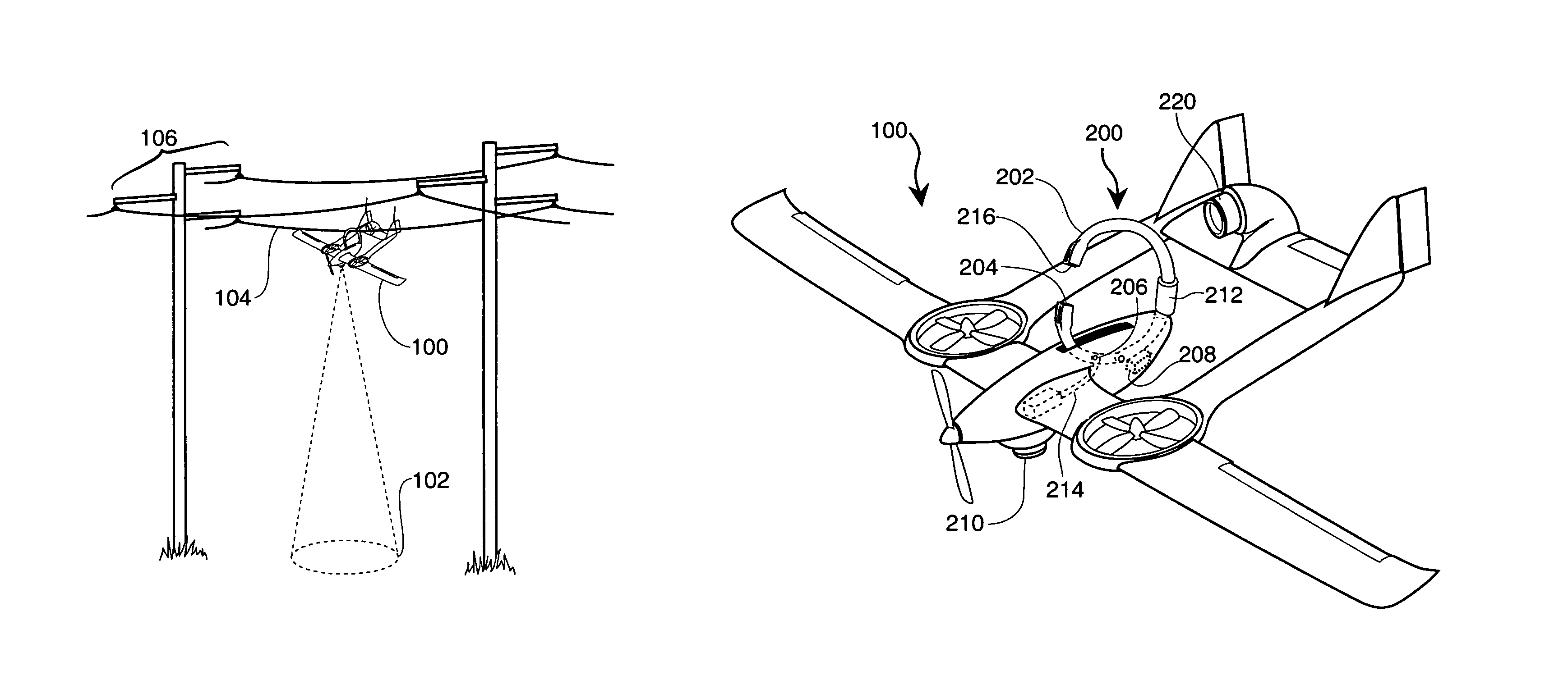
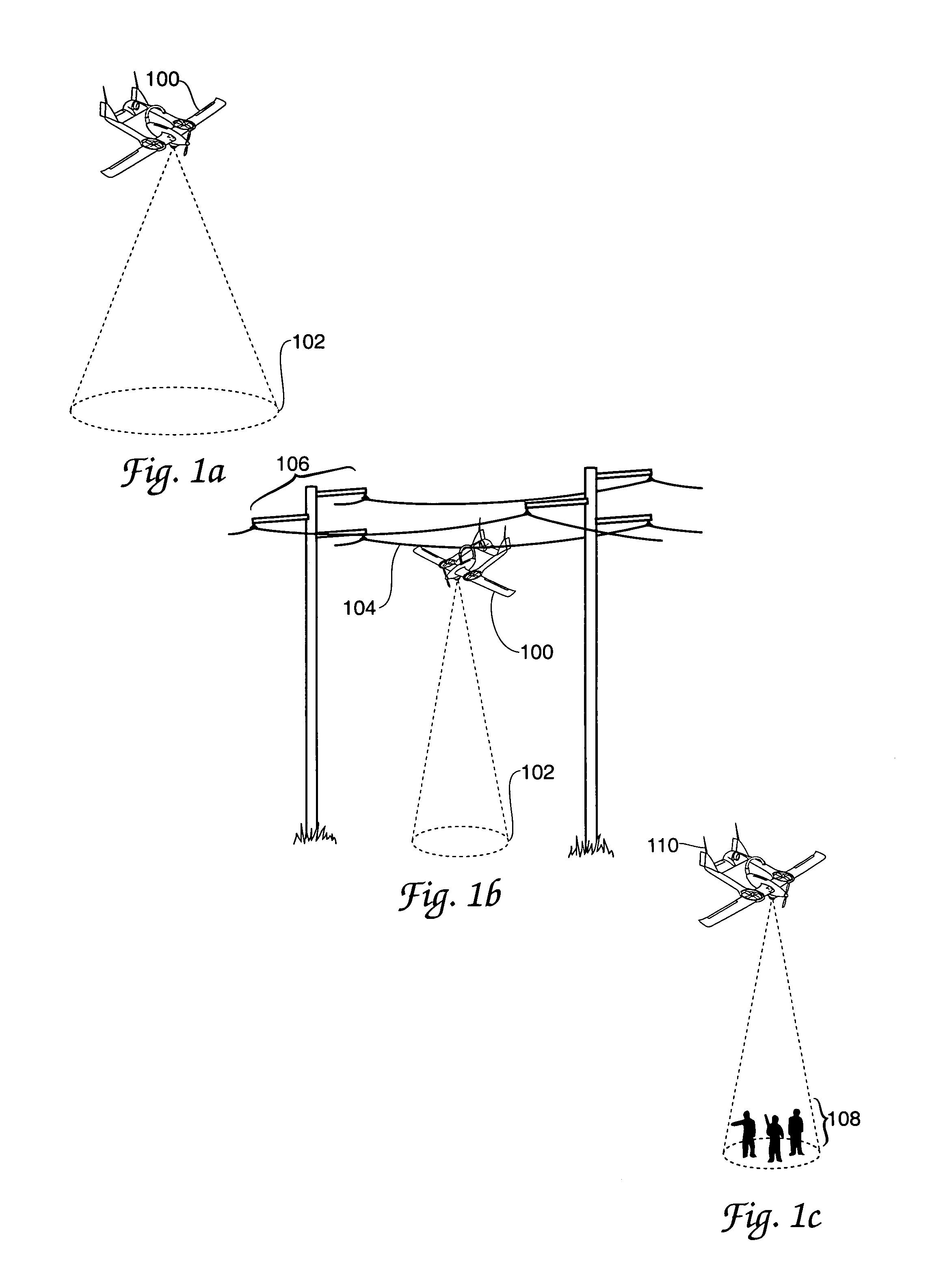
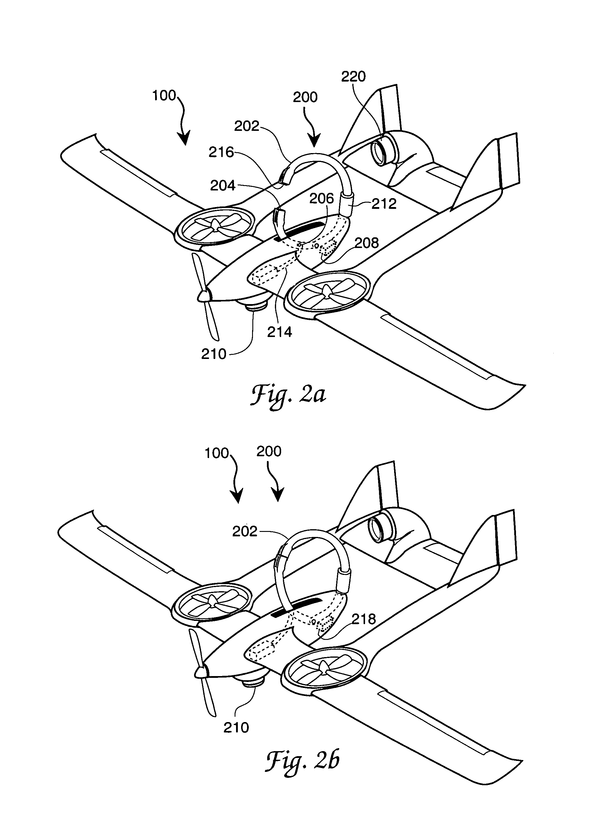
[0035]A key concept to the present invention is that “Numerous overhead power transmission lines that frequent most urban areas may be utilized by silent unmanned aerial vehicles to inductively recharge themselves while perched”. Theoretically these “power line-rechargeable” silent unmanned aerial vehicle units should be able to operate out in the urban field for an indefinite amount of time (i.e., 24 / 7 / 365 capability) with very infrequent “return-to-base” cycles being required. A typical urban military operation may for example involve launching swarms of present invention silent unmanned aerial vehicles weeks or even months before troops arrive to seek-out and terminate various combatants. For example, Special Operations troops may pre-program these vehicles to fly to local power lines near the urban areas of interest. If the duration of flight exhausts the battery power, then the silent unmanned aerial vehicles may simply locate the nearest power line for a temporary recharging. ...


PUM


Abstract

A rechargeable battery energized unmanned aerial vehicle having surveillance capability and an ability to clandestinely collect propulsion and other energy needs from a conveniently located and possibly enemy owned energy transmission line. Energy collection is by way of a parked vehicle engagement with the transmission line in a current flow dependent, magnetic field determined, rather than shunt, voltage dependent, conductor coupling. Surveillance during both a parked or docked condition and during aerial vehicle movement is contemplated.

Description

CLAIM OF PRIORITY[0001]This application claims the benefit of U.S. Provisional Patent Application No. 60 / 617,798, filed Oct. 4, 2004. The contents of this provisional application are hereby incorporated by reference herein.RIGHTS OF THE GOVERNENT[0002]The invention described herein may be manufactured and used by or for the Government of the United States for all governmental purposes without the payment of any royalty.CROSS REFERENCE TO RELATED PATENT DOCUMENT[0003]The present document is somewhat related to the copending and commonly assigned patent document “POWER LINE SENTRY CHARGING”, AFD 807, Ser. No. 11 / 169,260, U.S. Pat. No. 7,318,564. The contents of this somewhat related application are hereby incorporated by reference herein.BACKGROUND OF THE INVENTION[0004]Most modem-day wars are fought in urban environments. Large cities and small towns are the battlegrounds of choice by many present-day enemies. Unfortunately, this environment allows opponents to hide in numerous struc...

Claims


Application Information

Patent Timeline
IPC IPC(8): B64D41/00B60L9/00B64C25/68B64D45/00B64F1/02
CPCB60L11/1816B60L11/185B64C39/024B64D27/24B64F1/02B60L11/182B64C2201/182B60L2200/10B64C2201/021B64C2201/042B64C2201/088B64C2201/104B64C2201/108B64C2201/127B64C2201/165Y02T10/7005Y02T50/64Y02T90/121Y02T90/122Y02T90/128Y02T90/14Y02T10/7072B60L53/14B60L53/12B60L53/11Y02T10/70Y02T50/60B64U70/80B64U10/25B64U30/10B64U50/19B64U30/20B64U2101/30B64U70/30B64U50/13Y02T90/12
Inventor MARSHALL, PATRICK T.
Owner US SEC THE AIR FORCE THE
Why Eureka
Try Eureka