Guide means for centrifugal force separators, especially cyclone separators

a centrifugal force and separator technology, applied in centrifugal force sedimentation, volume/mass flow by differential pressure, liquid/fluent solid measurement, etc., can solve the problem that the known guide means do not work quite satisfactorily, improve the incident flow and inflow, improve the axial and tangential entry of the medium, and improve the incident flow behavior

Active Publication Date: 2008-07-15
EJK SERVICE GMBH
View PDF6 Cites 32 Cited by
  • Summary
  • Abstract
  • Description
  • Claims
  • Application Information

AI Technical Summary

Benefits of technology

[0014]The recess in the bottom plate improves the incident flow and inflow of the medium since the medium upon entry into the guide means has not only one flow component in the peripheral or rotational direction, but also in the axial direction.
[0015]In order to further improve the incident flow behavior, in one preferred embodiment of the invention it can be provided that the incident flow edge of the baffle plate runs tilted at least in the segment adjacent to the bottom plate in the direction of rotation of the medium. The incident flow edge can thus be given an alignment which is roughly at a right angle to the flow direction of the medium.
[0016]When the edge of the recess which runs to the inside leads away from the incident flow edge of the baffle plate, overall an enlarged entry opening for the medium into the guide means is formed which improves the axial and tangential entry of the medium and thus leads to lower output losses of the cyclone separator.

Problems solved by technology

On the other side this bottom plate however prevents undisrupted incident flow onto the guide means or inflow of the medium into the guide means in the form of a helical flow in the region of the outer periphery of the bottom plate, so that the known guide means does not work quite satisfactorily.

Method used


Image

  • Guide means for centrifugal force separators, especially cyclone separators
  • Guide means for centrifugal force separators, especially cyclone separators

Examples


Embodiment Construction

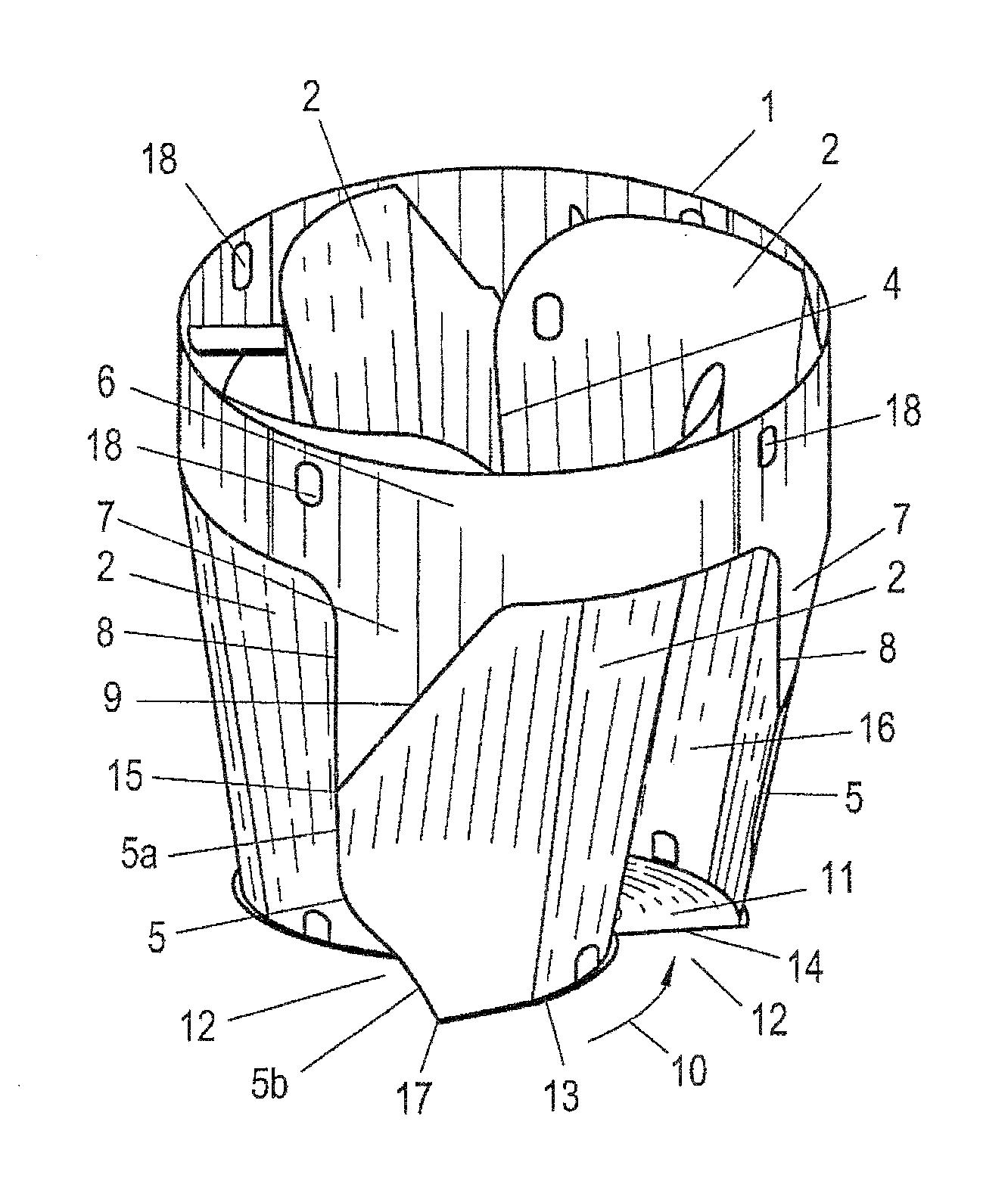
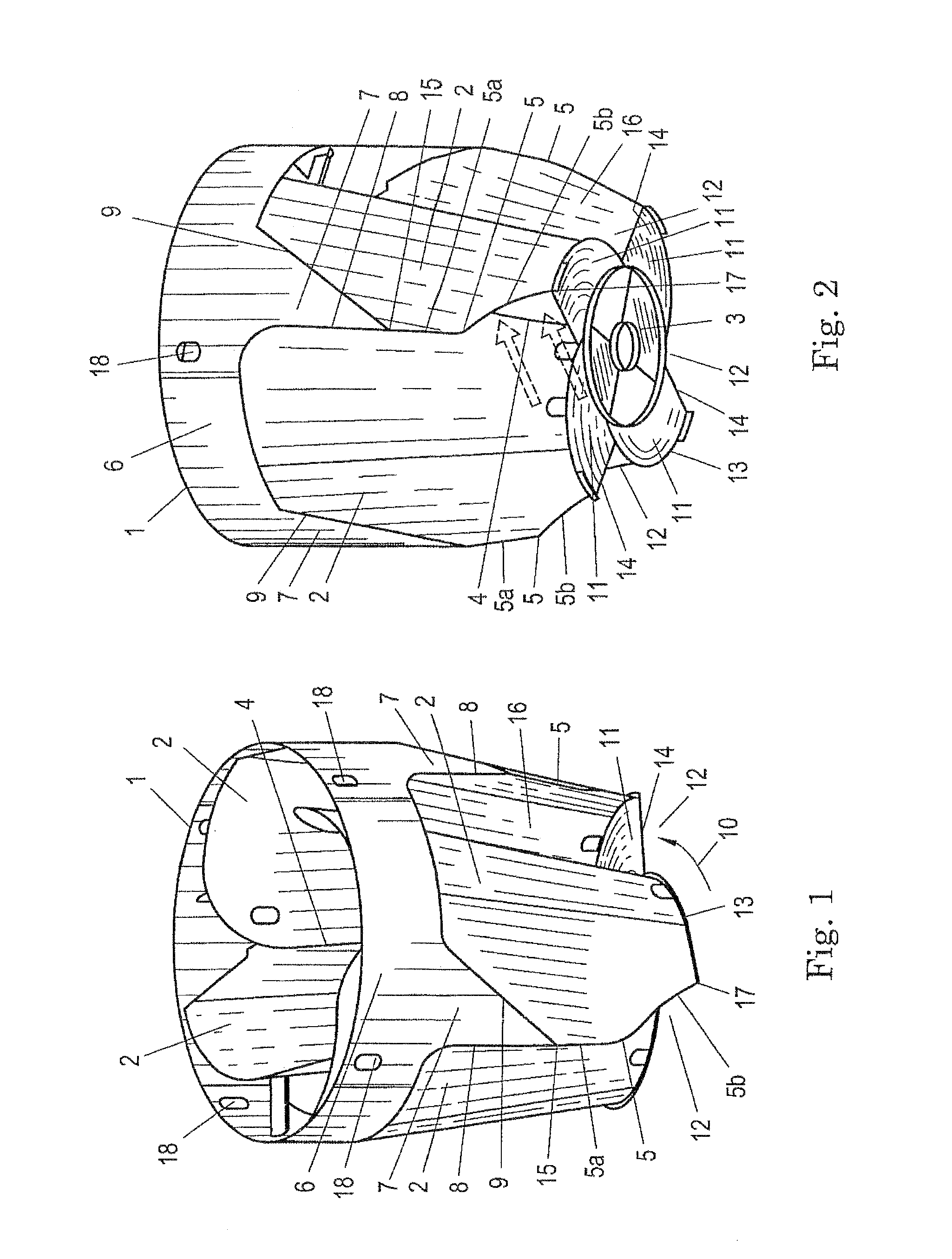
[0024]FIGS. 1 and 2 show a guide means which consists essentially of a cylindrical wall 1 in the upper area, four baffle plates 2 and one bottom plate 3. The four baffle plates 2 are all made the same and have a partially conical shape. This means that their radius of curvature in the area of the bottom plate 3 is less than in the opposing area near the cylindrical wall 1 and that they extend by an angle of roughly 100° to 110°. The axis of curvature of each baffle plate 2 is parallel to the center axis of the guide means which corresponds to the axis of the cylindrical wall 1.

[0025]The lengthwise edge 4 of the baffle plates 2 which is located within the guide means lies essentially in the plane of the axis of curvature of the respective baffle plate 2. The outside incident flow edge 5 which is opposite the lengthwise edge 4 in the embodiment shown in the drawings does not run in a straight line, but bent. The upper segment 5a which is adjacent to the cylindrical wall 1 is aligned e...


PUM

PropertyMeasurementUnit
angleaaaaaaaaaa
angleaaaaaaaaaa
specific weightaaaaaaaaaa

Abstract

A guide means of a centrifugal force separator or cyclone separator for separating at least one substance from a gaseous or liquid medium under the action of centrifugal forces has two or more baffle plates (2) with a radius which decreases from the center axis of the guide means, viewed in the direction of rotation of the medium. Between these baffle plates (2) entry openings (16) into the guide means are formed for the medium from which the substance has been largely removed into the guide means. There is a bottom plate (3) on the end of the guide means which projects into the interior of the device. To improve incident flow or inflow of the medium into the guide means, the bottom plate (3) in the area of the entry openings (16) has recesses (12).

Description

BACKGROUND OF THE INVENTION[0001]1. Field of the Invention[0002]The invention relates to a guide means of a device, especially of a centrifugal force separator or cyclone separator, for separating at least one substance from a gaseous or liquid medium under the action of centrifugal forces, the substance having a higher specific weight than the medium, the guide means having at least one curved baffle plate with a radius which decreases from the center axis of the guide means, viewed in the direction of rotation of the medium, with at least one entry opening into the guide means for the medium from which the substance has been largely removed, and with a bottom plate on the end of the guide means which projects into the interior of the device.[0003]The invention furthermore relates to an immersion pipe of a device, especially of a centrifugal force separator or cyclone separator, for separating at least one substance from a gaseous or liquid medium under the action of centrifugal fo...

Claims


Application Information

Patent Timeline
Patent Type & Authority Patents(United States)
IPC IPC(8): B04C5/103B01D17/038B01D21/26B01D45/12B04C5/13
CPCB04C5/13B04C5/103B04C2005/136
Inventor KEUSCHNIGG, JOSEF
Owner EJK SERVICE GMBH
Why Eureka
Try Eureka