Blood coagulation test cartridge, system, and method

a blood coagulation and test cartridge technology, applied in the field of blood coagulation test cartridges, systems and methods, can solve the problems of increased probability of post-operative bleeding problems, delayed or inaccurate detection of coagulation, and loss of endothelium integrity, etc., to achieve rapid and reliable detection, simple practice, and simple

Active Publication Date: 2008-07-15
MEDTRONIC INC
View PDF178 Cites 123 Cited by
  • Summary
  • Abstract
  • Description
  • Claims
  • Application Information

AI Technical Summary

Benefits of technology

[0024]Therefore, the present invention provides a compact, inexpensive, disposable, test cartridge in which a test sample, particularly a blood or biologic test sample, to be tested is deposited and systems and methods for detecting a change in test sample viscosity. In a particular application, the present invention provides systems and methods for measuring a test coagulation time of such a test sample that are simple to practice, rapid, and reliable.

Problems solved by technology

When a blood vessel is damaged, however, the endothelium loses its integrity and platelets are activated by contact with tissue underlying the damaged site.
A deficiency of functional platelets in the blood may be indicative of an increased probability of a post-operative bleeding problem.
The detection of coagulation would be delayed or inaccurate if the sample coagulates between movement cycles.
The magnetic force is insufficient to attract the ball when the fluid in the tube changes viscosity, e.g., due to clotting, and the failure of the member to stay within the magnetic field is detected magnetically with a reed switch.
The side-to-side drifting movement may affect the rise time and the fall time, which could add error to the coagulation time measured.
The washer may eventually stop moving as a clot forms about it, and no additional information can be obtained on the coagulation process in the sample.

Method used


Image

  • Blood coagulation test cartridge, system, and method
  • Blood coagulation test cartridge, system, and method
  • Blood coagulation test cartridge, system, and method

Examples


Embodiment Construction

[0056]In the following detailed description, references are made to illustrative embodiments of methods and apparatus for carrying out the invention. It is understood that other embodiments can be utilized without departing from the scope of the invention. Preferred methods and apparatus are described for performing blood coagulation tests of the type described above.

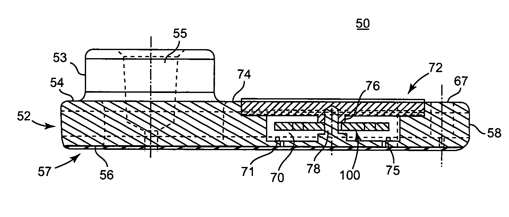
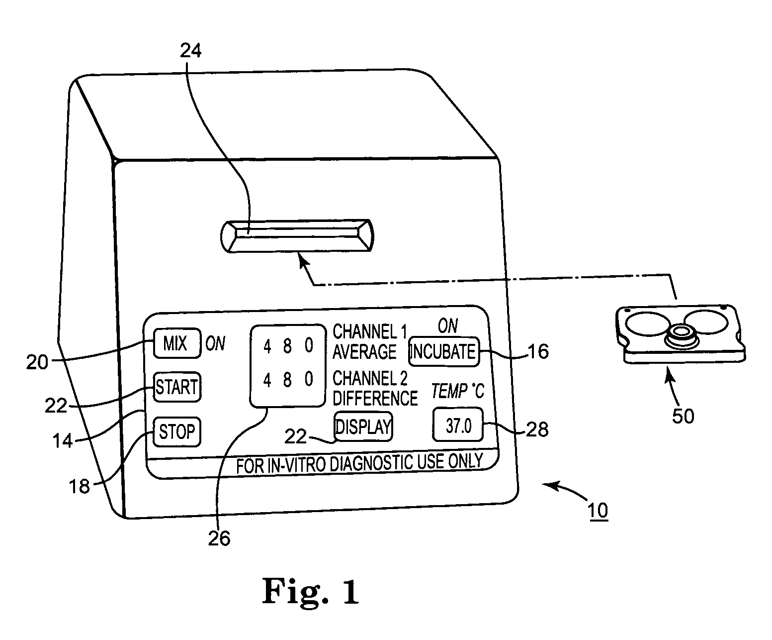
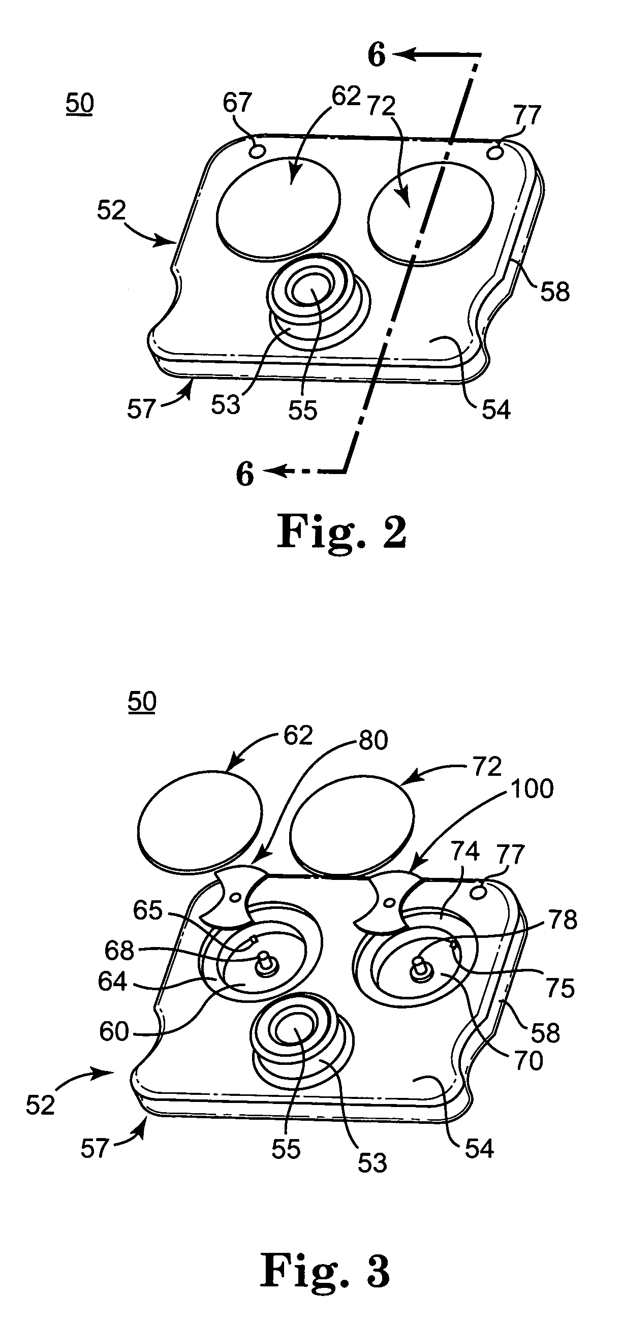
[0057]FIG. 1 is perspective view of the simplified automatic coagulation time test instrument 10 that can advantageously be used in the practice of the present invention. The test instrument 10 is portable and is operated by battery power or power from an AC line. The test instrument 10 has a cartridge receptacle 24 that receives a test cartridge 50 shown in more detail FIGS. 2-6 inserted through the external slot of he cartridge receptacle 24. The test instrument 10 can incubate test samples within the test chambers of the test cartridge 50. The test instrument 10 also conducts coagulation time tests on test samples in...


PUM

PropertyMeasurementUnit
temperaturesaaaaaaaaaa
temperatureaaaaaaaaaa
sweeping movementaaaaaaaaaa

Abstract

A system and method for determining a coagulation time, e.g., TT, PT, aPTT, and ACT, of a blood test sample deposited in a test cartridge is disclosed. A cartridge housing having upper and lower major sides and a minor sidewall encloses a test chamber having a test chamber pivot element and is provided with a cartridge port for introducing a test sample into the test chamber,. Ferromagnetic agitator vane leaflets extend from an agitator pivot element supported by the test chamber pivot element intermediate the upper and lower major sides for rotational motion. The agitator vane leaflets can be swept, in response to an external magnetic field, through the test sample in the absence of coagulation. A timer is started when the agitator movement is commenced whereupon the agitator moves freely. Resistance to agitator movement due to coagulation is detected, and the coagulation time is measured.

Description

REFERENCE TO RELATED APPLICATION[0001]This application claims the benefit of U.S. Provisional Application No. 60 / 563,320 filed Apr. 19, 2004. Reference is hereby made to commonly assigned U.S. patent application Ser. No. 10 / 826,994 filed on Apr. 19, 2004 for BLOOD COAGULATION TEST CARTRIDGE, SYSTEM, AND METHOD in the name of Cynthia T. Clague et al.FIELD OF THE INVENTION[0002]This invention relates to detecting changes in viscosity of biologic fluid test samples, e.g., detecting coagulation and coagulation-related activities including agglutination and fibrinolysis of human blood test samples, and more particularly to improved methods and apparatus for obtaining a coagulation time of a blood test sample.BACKGROUND OF THE INVENTION[0003]Blood coagulation is a complex chemical and physical reaction that occurs when blood (herein, “blood” shall mean whole blood, citrated blood, platelet concentrate, plasma, or control mixtures of plasma and blood cells, unless otherwise specifically ca...

Claims


Application Information

Patent Timeline
Patent Type & Authority Patents(United States)
IPC IPC(8): G01N33/86G01N11/14G01N11/16G01N33/49
CPCG01N11/14G01N33/4905G01N11/16Y10T436/111666
Inventor WRIGHT, DAVID W.KRIEWALL, TIMOTHY J.CHEEK, DANIEL S.
Owner MEDTRONIC INC
Why Eureka
Try Eureka