High efficiency single-inductor dual-control loop power converter

a dual-control loop, high-efficiency technology, applied in the direction of electric variable regulation, process and machine control, instruments, etc., can solve the problems of rapid loss of overall power efficiency and low overall power efficiency of single-loop synchronous regulated switching converters, and achieve the effect of lowering the overall power efficiency of sidl

Active Publication Date: 2008-07-15
ALPHA & OMEGA SEMICON LTD
View PDF4 Cites 20 Cited by
  • Summary
  • Abstract
  • Description
  • Claims
  • Application Information

AI Technical Summary

Benefits of technology

[0011]In an embodiment, in response to any given level of sensed freewheeling current, the real-time control loop adjusts for just an adequate level of conductance of the power shunt transistor su

Problems solved by technology

Clearly, the above ELC acts to undesirably lower the overall power efficiency of the single-loop synchronous regulated switching

Method used


Image

  • High efficiency single-inductor dual-control loop power converter
  • High efficiency single-inductor dual-control loop power converter
  • High efficiency single-inductor dual-control loop power converter

Examples


Embodiment Construction

[0024]The description above and below plus the drawings contained herein merely focus on one or more currently preferred embodiments of the present invention and also describe some exemplary optional features and / or alternative embodiments. The description and drawings are presented for the purpose of illustration and, as such, are not limitations of the present invention. Thus, those of ordinary skill in the art would readily recognize variations, modifications, and alternatives. Such variations, modifications and alternatives should be understood to be also within the scope of the present invention.

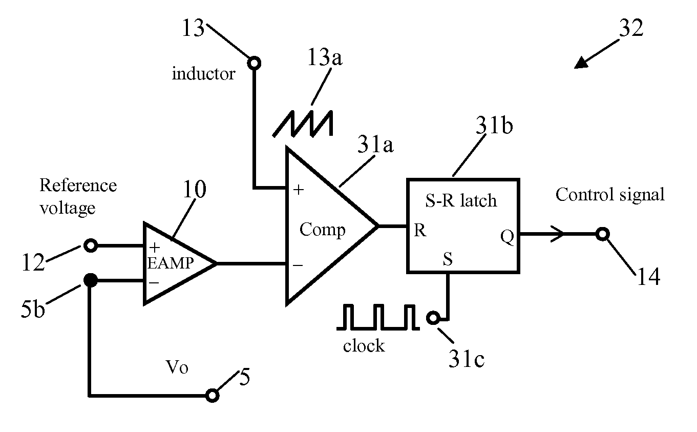
[0025]FIG. 3 is a top level circuit architecture illustrating an embodiment of the single-inductor dual-control loop converter (SIDL) 30 of the present invention. As referenced to a power ground 2, the SIDL 30 converts an unregulated DC input 3 into a regulated DC output voltage 5 to a power load 4 with a load current Io 15. The output end of the SIDL 30 is an energy storage loop furthe...


PUM


Abstract

A high efficiency single-inductor dual-control loop power converter (SIDL) is proposed for converting unregulated DC input into regulated DC output to a power load. The SIDL includes:
  • an energy storage loop having: a power inductor, a power capacitor and a power diode.
A PWM switching power regulating loop for converting the unregulated DC input into the regulated DC output.
  • a power-efficiency maximizing loop in parallel connection with the power diode.
The power-efficiency maximizing loop includes: a power shunt transistor in parallel connection with the power diode and a real-time control loop adjusting, in response to a freewheeling current through the power diode, conductance of the power shunt transistor in a manner that a higher freewheeling current results in a higher conductance of the power shunt transistor.

Description

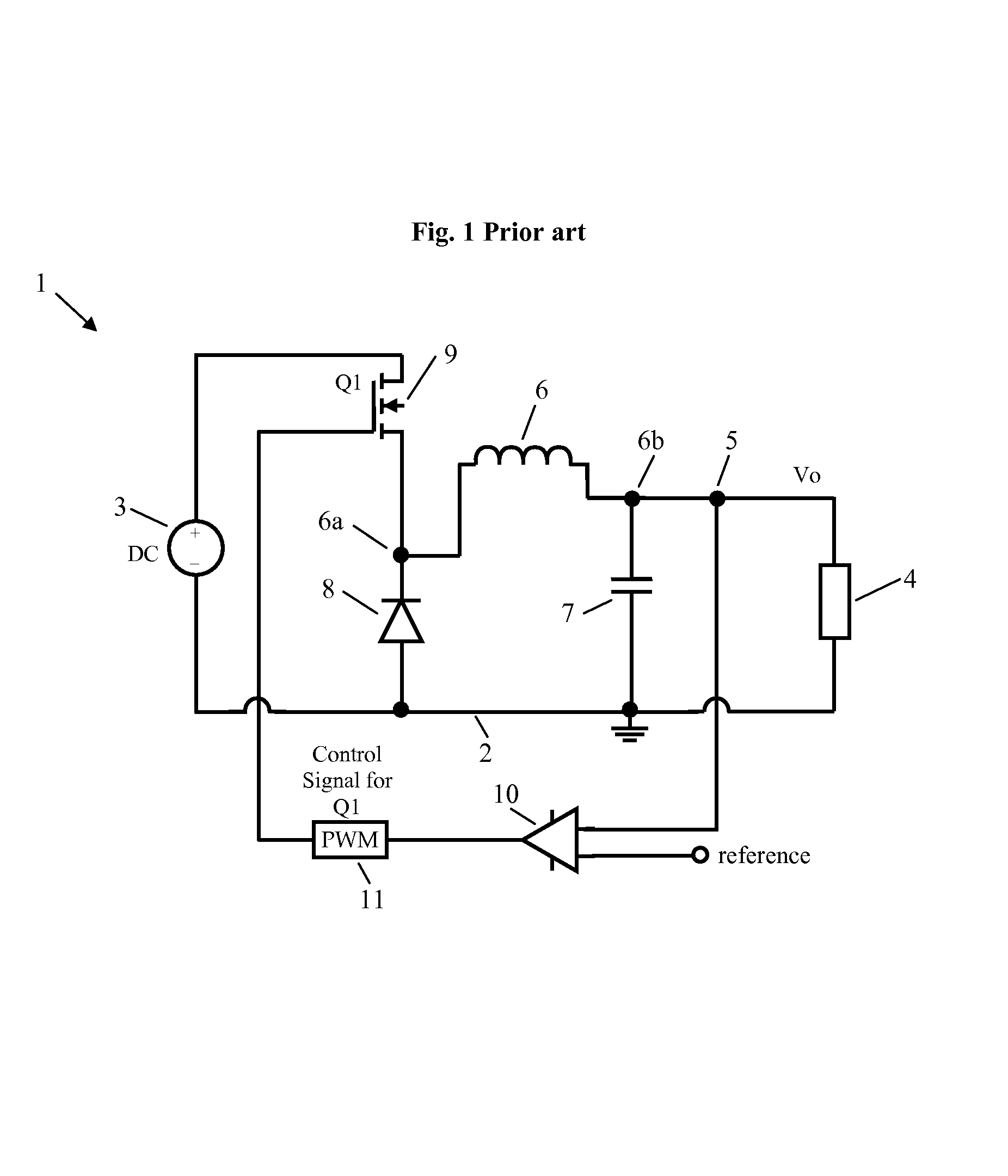
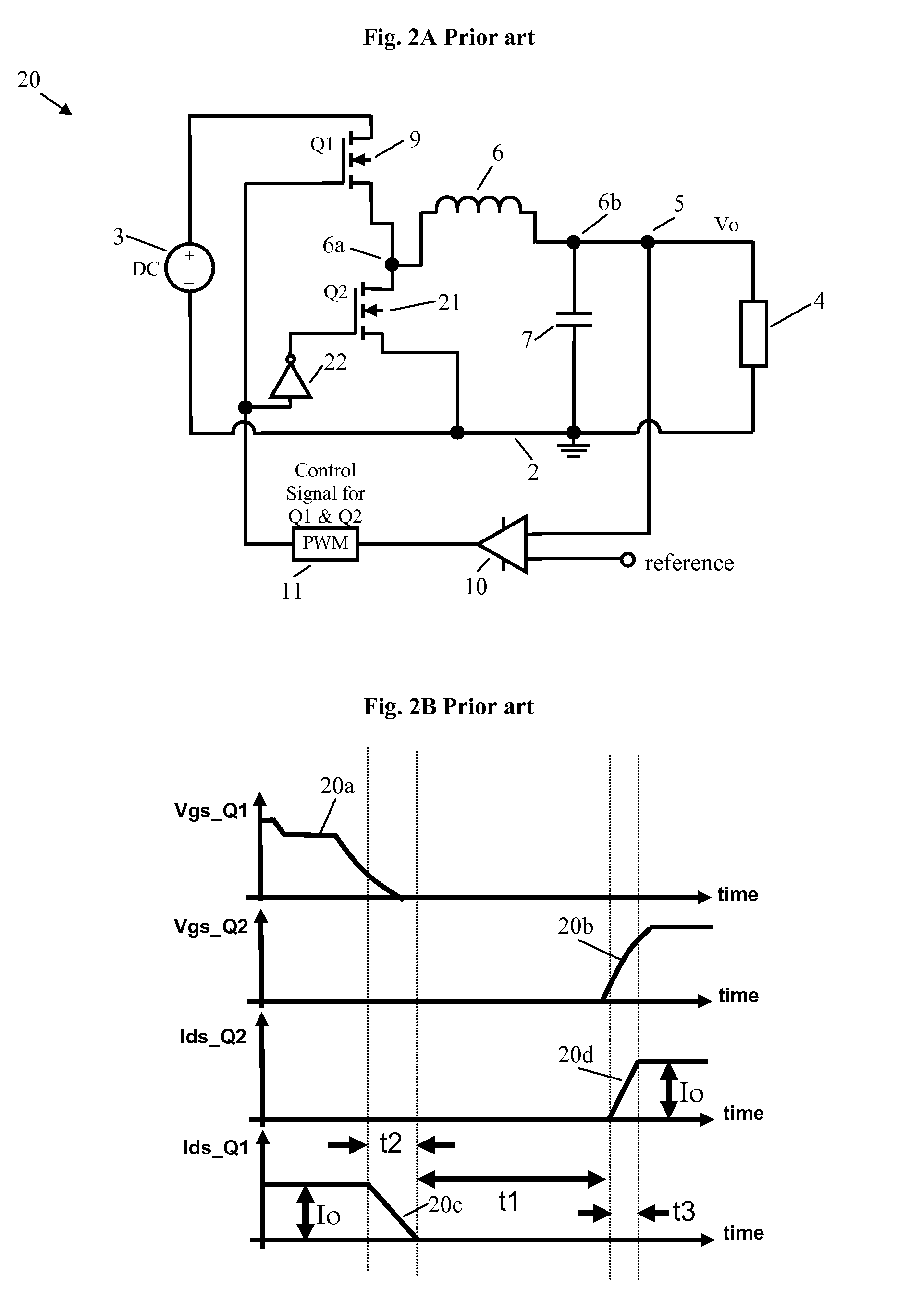
CROSS REFERENCE TO RELATED APPLICATIONSField of Invention[0001]This invention relates generally to the field of electrical power supply. More specifically, the present invention is directed to the design of a switching power supply.BACKGROUND OF THE INVENTION[0002]Owing to its compact size, low weight and generally high efficiency, switching power supplies have enjoyed ever increasing market adoption in the consumer electronics industry. This is specially so in portable applications where compact size, low weight and battery life are all on top of the list of considerations.[0003]As a first illustration of prior art switching power supply, FIG. 1 illustrates a non-synchronous, single-loop regulated switching converter 1. The single-loop regulated switching converter 1 operates to convert an unregulated DC input 3 into a regulated DC output voltage 5 supplying a power load 4 with power ground 2. A controlled power output transistor 9 drives the power load 4 through a series, parallel...

Claims


Application Information

Patent Timeline
IPC IPC(8): G05F1/00
CPCH02M3/1588Y02B70/16Y02B70/1466H02M2001/0032H02M1/0032Y02B70/10
Inventor ZHANG, ZHIYECHANG, YU-CHENG
Owner ALPHA & OMEGA SEMICON LTD
Why Eureka
Try Eureka