Current sensor and method of manufacturing the same
a current sensor and sensor technology, applied in pulse generators, pulse techniques, instruments, etc., can solve the problems of inability to accurately detect current, and limited gap separation distance to the thickness of hall ic, so as to reduce separation distance, accurate positioning, and increase sensitivity
- Summary
- Abstract
- Description
- Claims
- Application Information
AI Technical Summary
Benefits of technology
Problems solved by technology
Method used
Image
Examples
first embodiment
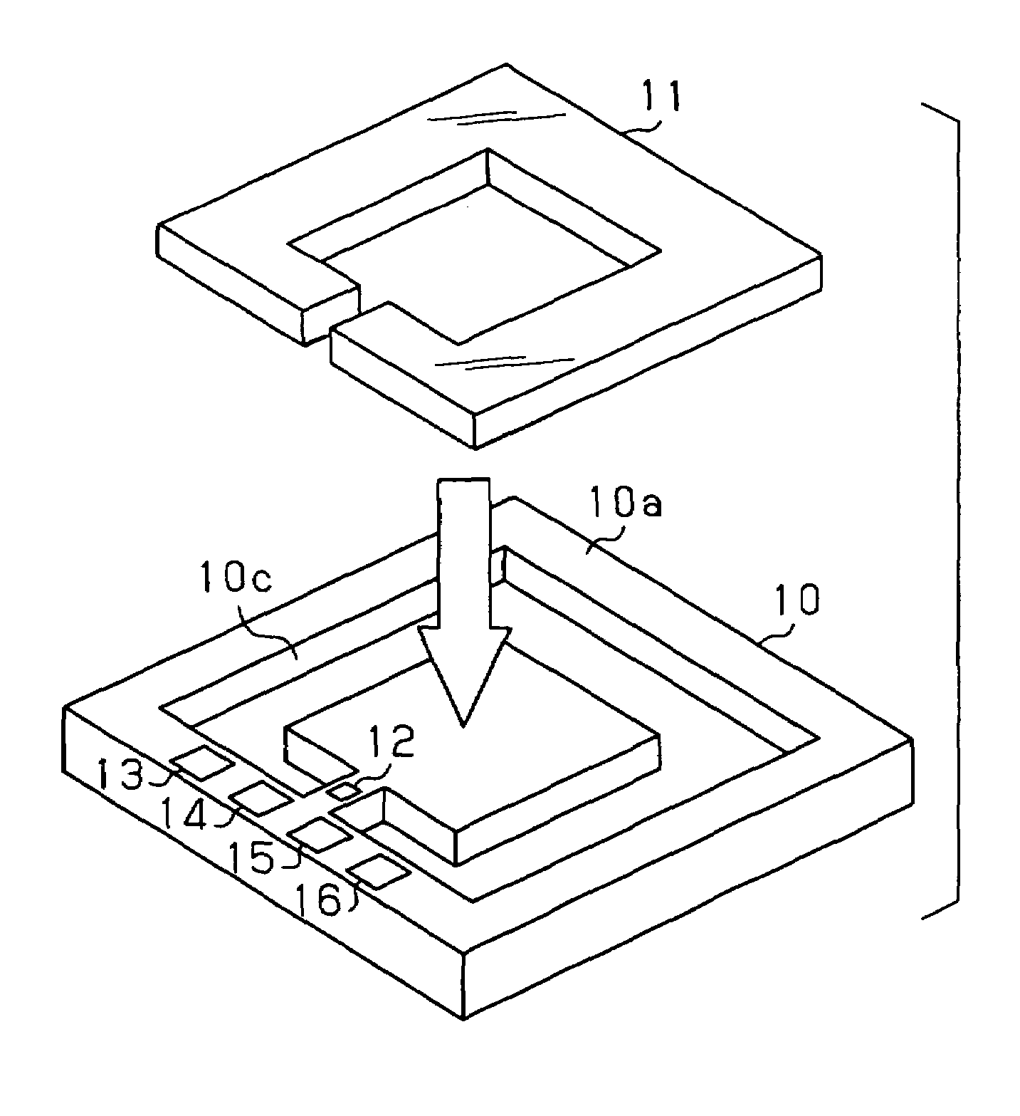
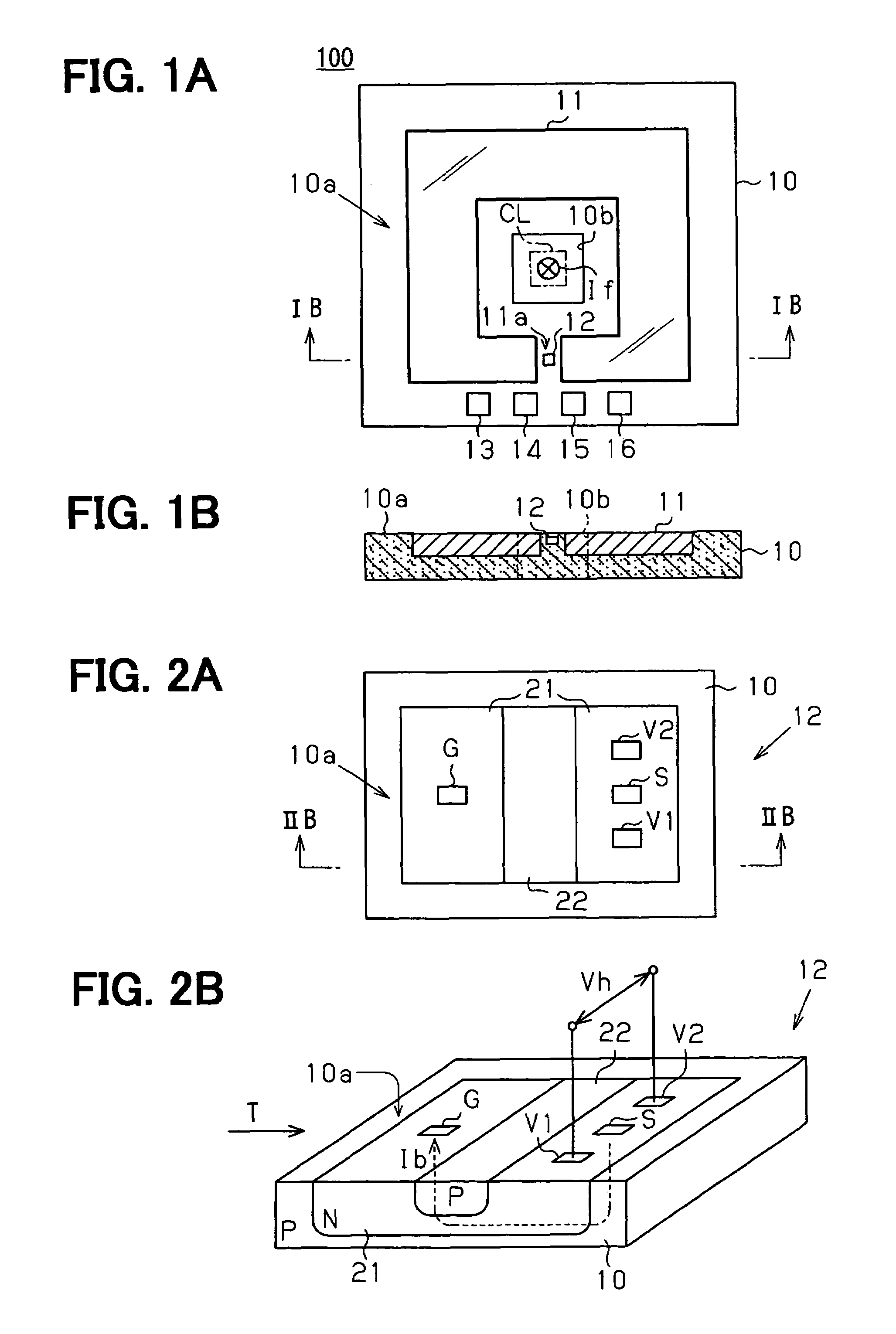
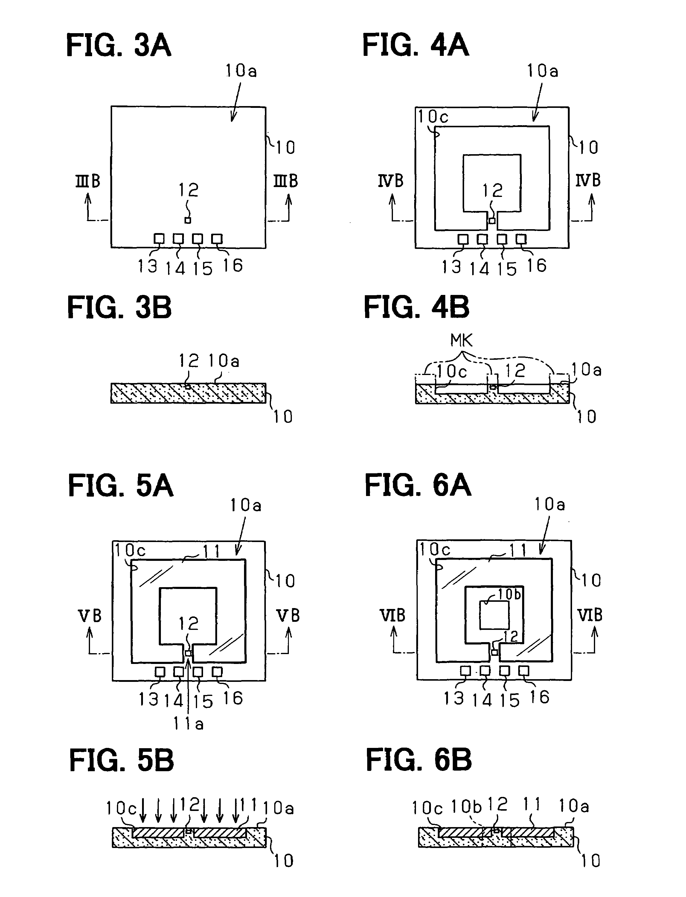
[0023]Referring to FIGS. 1A and 1B, a current sensor 100 includes a semiconductor substrate 10 with a surface 10a and a center hole 10b, a ring-shaped magnetic core 11 with a gap 11a, a vertical Hall element 12.
[0024]The center hole 10b penetrates through the substrate 10 in a thickness direction of the substrate 10. A conductor CL through which a current If to be detected flows is inserted through the center hole 10b. The magnetic core 11 is made of a magnetic material such as permalloy and formed to the surface 10a to surround the center hole 10b. The Hall element 12 is placed in the gap 11a such that a control current Ib shown in FIG. 2B flows in a direction perpendicular to the surface 10a. The Hall element 12 has terminals electrically connected to wire bonding pads 13-16 formed on the surface 10a.
[0025]FIGS. 2A and 2B illustrate the Hall element 12 in detail.
[0026]As shown in FIG. 2B, when the control current Ib having a perpendicular component to the surface 10a is supplied ...
second embodiment
[0043]Referring to FIGS. 8A-9D, a current sensor 200 includes a semiconductor substrate 30 with a surface 30a, the magnetic core 11, and the Hall element 12.
[0044]First and second connection terminals 31, 32 are formed on the surface 30a of the substrate 30. As shown in FIG. 8A, the first and second connection terminals 31, 32 are positioned inside and outside the magnetic core 11, respectively. Specifically, the first and second connection terminals 31, 32 are positioned on the opposite side of the magnetic core 11.
[0045]As shown in FIG. 8B, a conductive member 33 for electrically connecting the first and second connection terminals 31, 32 is formed in the substrate 30 to pass under the magnetic core 11. The conductive member 33 has first and second end portions 33a, 33c (see, FIG. 9D) extending perpendicular to the surface 30a and a middle portion 33b (see, FIG. 9D) extending parallel to the surface 30a. The first and second end portions 33a, 33c are connected to the first and sec...
PUM
 Abstract
Description
Claims
Application Information
 - R&D
- Intellectual Property
- Life Sciences
- Materials
- Tech Scout
- Unparalleled Data Quality
- Higher Quality Content
- 60% Fewer Hallucinations
Browse by: Latest US Patents, China's latest patents, Technical Efficacy Thesaurus, Application Domain, Technology Topic, Popular Technical Reports.
© 2025 PatSnap. All rights reserved.Legal|Privacy policy|Modern Slavery Act Transparency Statement|Sitemap|About US| Contact US: help@patsnap.com


