
Magnetic type angle sensor

a technology of angle sensor and magnetic field, which is applied in the direction of galvano-magnetic hall-effect devices, gear teeth, instruments, etc., can solve the problems of increased cost, increased production cost, and increased disadvantageous number of production steps, and achieves low cost and easy assembly.

Active Publication Date: 2008-07-15
FANUC LTD
View PDF13 Cites 16 Cited by
  • Summary
  • Abstract
  • Description
  • Claims
  • Application Information

AI Technical Summary

Benefits of technology

This approach simplifies assembly and reduces production costs by integrating angle and one-rotation signal generators on a single member, enabling efficient and cost-effective manufacturing and installation on rotary shafts.

Problems solved by technology

Accordingly, there is the defect of an increase in the production costs.
Further, as the rotary shaft of the motor, etc., has to be fit with the two sensor rings 20a and 20b, two attachment steps are involved and therefore the number of production steps is disadvantageously increased.
As a result, the cost is raised by that extent.

Method used


Image

  • Magnetic type angle sensor
  • Magnetic type angle sensor
  • Magnetic type angle sensor

Examples


Embodiment Construction

[0028]An embodiment of the present invention will be described below in conjunction with the drawings.

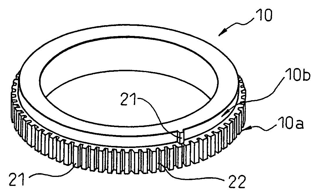
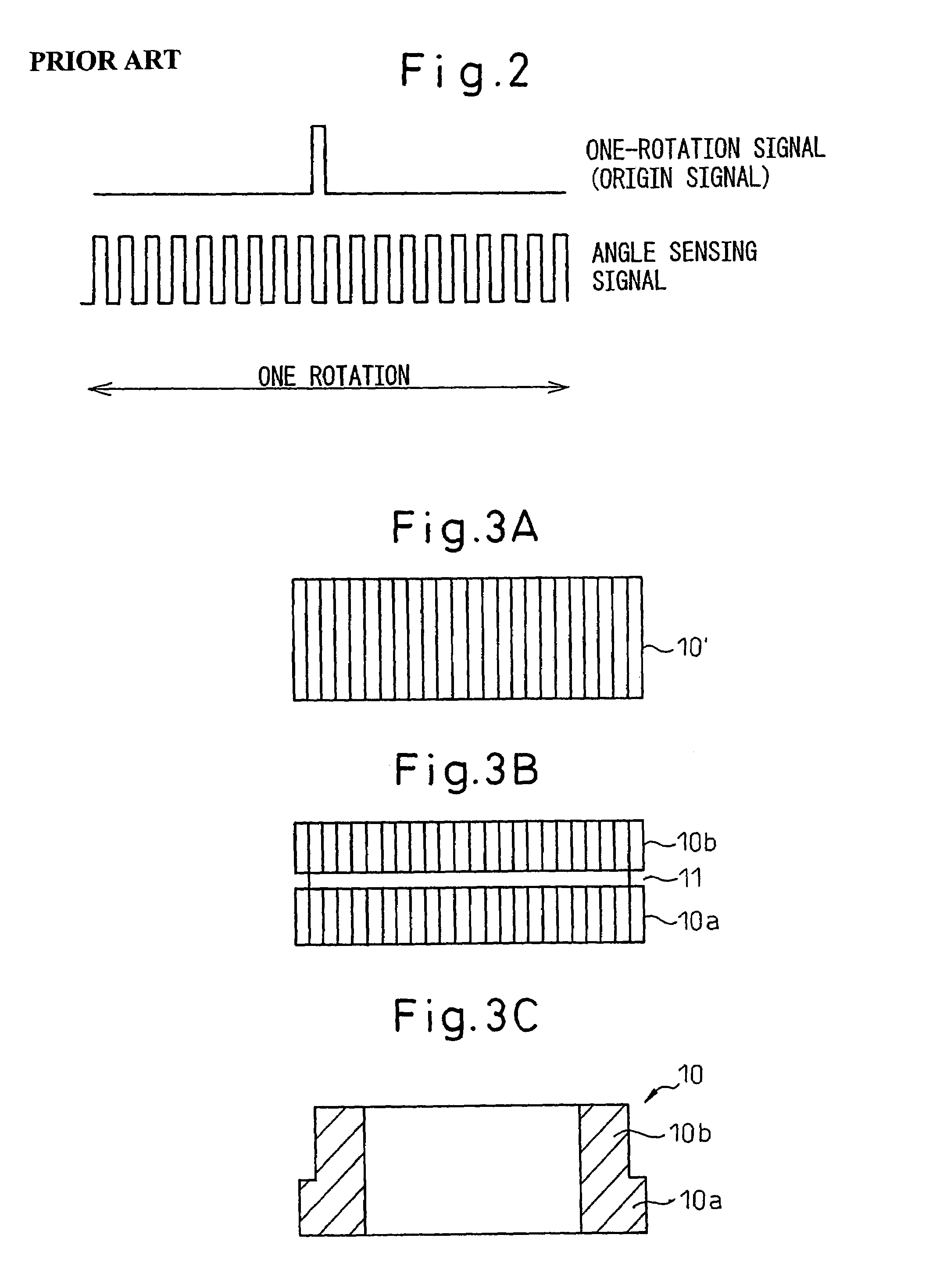
[0029]FIGS. 3A to 3C are views for illustrating a process of production of a rotary body of a magnetic type angle sensor according to an embodiment of the present invention. First, as shown in FIG. 3A, a magnetic material is used to prepare a ring 10′ for forming the rotary body. This ring 10′ has a thickness (length in an axial direction of the ring 10′) over the sum of a thickness of an angle signal generator forming a first sensed part and a thickness of a one-rotation signal generator forming a second sensed part and is formed on an outer circumferential surface thereof with gear-shaped recessed parts and projecting parts alternately at equal intervals. The gear shape may be formed by the gear cutting of the outer circumferential surface of the ring 10′. Alternatively, the gear shape may be formed by using a sintered metal powder having magnetism as the material of the ring 10′ ...


PUM


Abstract

A magnetic type angle sensor includes a rotary body having a first sensed part provided on a circumferential surface thereof with projecting parts and recessed parts at equal intervals in a circumferential direction thereof and a second sensed part provided on a circumferential surface thereof with a projecting parts at just one location, and a magnetic sensing device for sensing a change in a magnetic field along with rotation of the rotary body. The rotary body is formed with a plurality of projecting parts and recessed parts in a gear shape by gear cutting on the circumferential surface, then is cut with a groove at the center thereof in the axial direction thereof and has all projecting parts in a half section in the axial direction thereof cut off except for one.

Description

[0001]This is a divisional application of Application No. 11 / 156,492, filed on Jun. 21, 2005, now abandoned the entirety being incorporated by reference herein.BACKGROUND OF THE INVENTION[0002]1. Field of the Invention[0003]The present invention relates to a magnetic type angle sensor using magnetism to sense a rotational angle and rotational position of a rotary shaft or other rotary member.[0004]2. Description of the Related Art[0005]As a magnetic type angle sensor using magnetism to sense the rotational angle of a rotary member, there is known a magnetic type encoder or the like for sensing the rotational position and rotational angle of a motor shaft, a rotary shaft driven by a motor, or another rotary member.[0006]FIGS. 1A to 1C are views for illustrating the operating principle of an angle sensor using magnetism to sense a rotational angle. A rotary body (hereinafter referred to as a “sensor ring”) 1 of an angle sensor mounted on a rotary shaft, etc. is comprised of pure iron ...

Claims


Application Information

Patent Timeline
Patent Type & Authority Patents(United States)
IPC IPC(8): G01B7/30B21D53/28B23F1/00G01B7/14G01D5/245H10N52/00
CPCG01D5/2457Y10T29/49467Y10T409/102226Y10T29/49476Y10T409/101431
Inventor TANIGUCHI, MITSUYUKIIMAI, KEISUKENAGATOMO, ICHIROU
Owner FANUC LTD
Learn More