Optical observation apparatus with video device

Active Publication Date: 2008-07-15
CARL-ZEISS-STIFTUNG TRADING AS CARL ZEISS
View PDF8 Cites 8 Cited by
  • Summary
  • Abstract
  • Description
  • Claims
  • Application Information

AI Technical Summary

Benefits of technology

[0009]The configuration of the optical observation apparatus of the invention makes it possible for the object which is being observed to be continuously recorded without assistance from the user, and put into intermediate storage in the first memory. Data which have already been stored in the first memory over a predetermined period of time, for example the oldest recordings in the first memory, are in that case respectively overwritten by fresh data, for example a new recording. If now for example during an operation a situation which the surgeon conducting the procedure would like to record occurs, he can still secure the recording of the situation during the entire period of time in which it is stored in the first memory, by causing transfer preferably of the entire content of the first memory into the second memory. If the images are in intermediate storage in the first memory for example for five minutes, then the first image recorded of the situation is erased again five minutes after it was recorded. Therefore the user of the optical observation apparatus still has five remaining minutes to trigger transfer into the second memory. In particular recording of a situation which occurs only briefly can still be secured in that way even if the situation is already past.
[0010]In order to guarantee transfer of the data from the first memory to the second memory as quickly as possible, it is advantageous if the data communication between the first and second memories is designed for transmission at a high data rate. It is also advantageous if the second memory has a memory capacity which i

Problems solved by technology

However, no transfer of the content of the first memory to the second m

Method used


Image

  • Optical observation apparatus with video device
  • Optical observation apparatus with video device
  • Optical observation apparatus with video device

Examples


Example

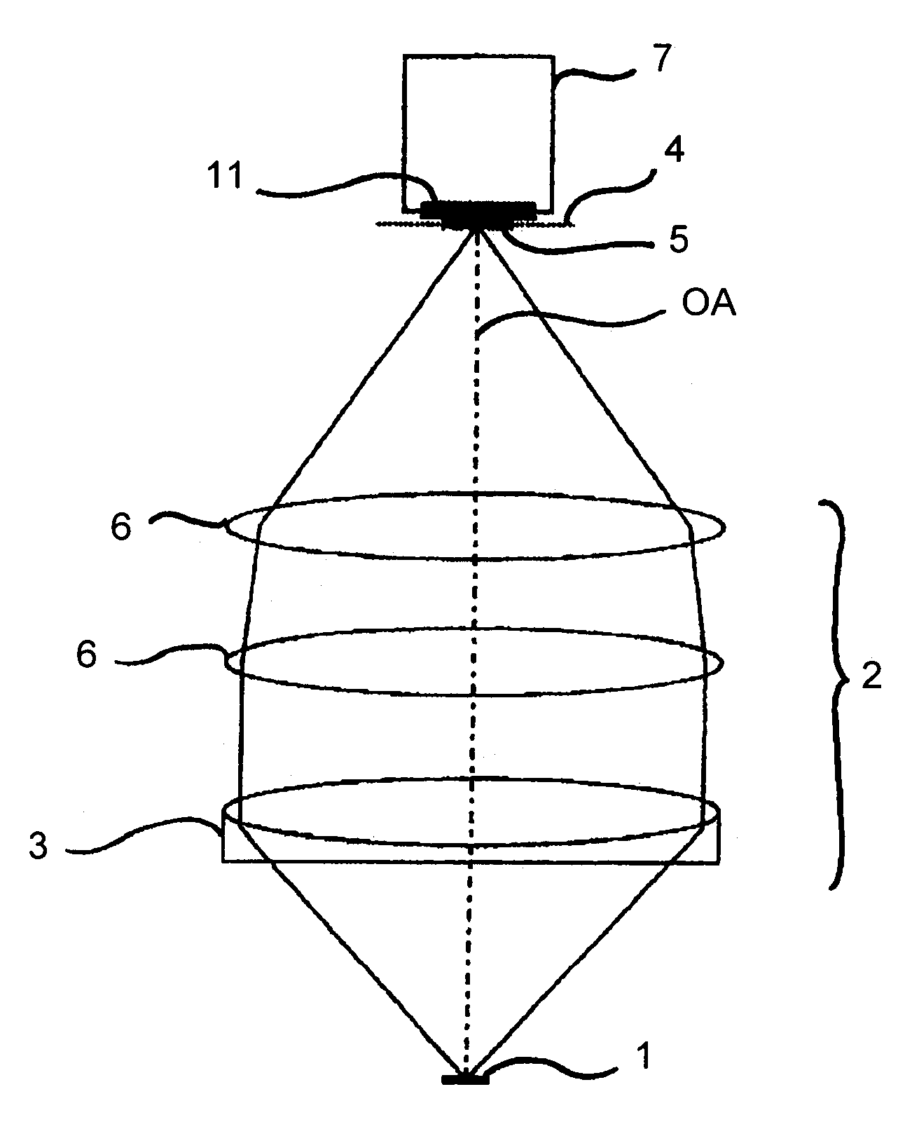
[0020]An operation microscope is diagrammatically shown in FIG. 1, as a first embodiment of the invention. The Figure represents a section taken along the optical axis OA of the operation microscope. The Figure shows an object 1 of which the image is to be produced, an optical system 2 with an achromatic objective lens 3 and further lenses 6 (not to be described in greater detail), as well as an intermediate image 5 of the object 1, which is produced by the optical system 2 in an intermediate image plane 4.

[0021]The operation microscope further includes a video device 7 with an active camera surface 11. The active camera surface 11 can either be the surface of a camera objective lens which produces the intermediate image 5 on a sensor surface, for example a CCD chip, of the video device 7, or the sensor surface itself. In the latter case, the intermediate image 5 is recorded directly with the sensor surface.

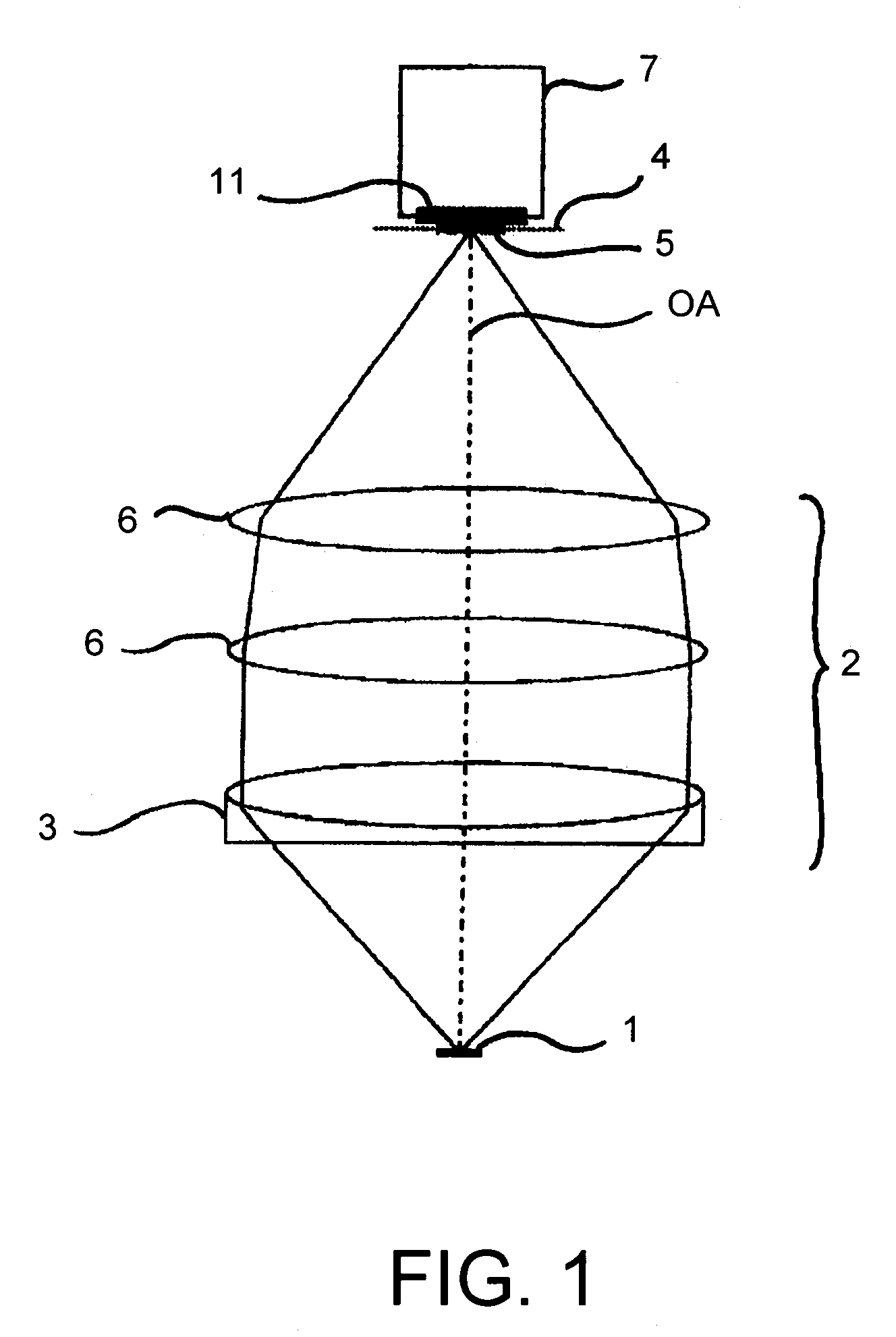
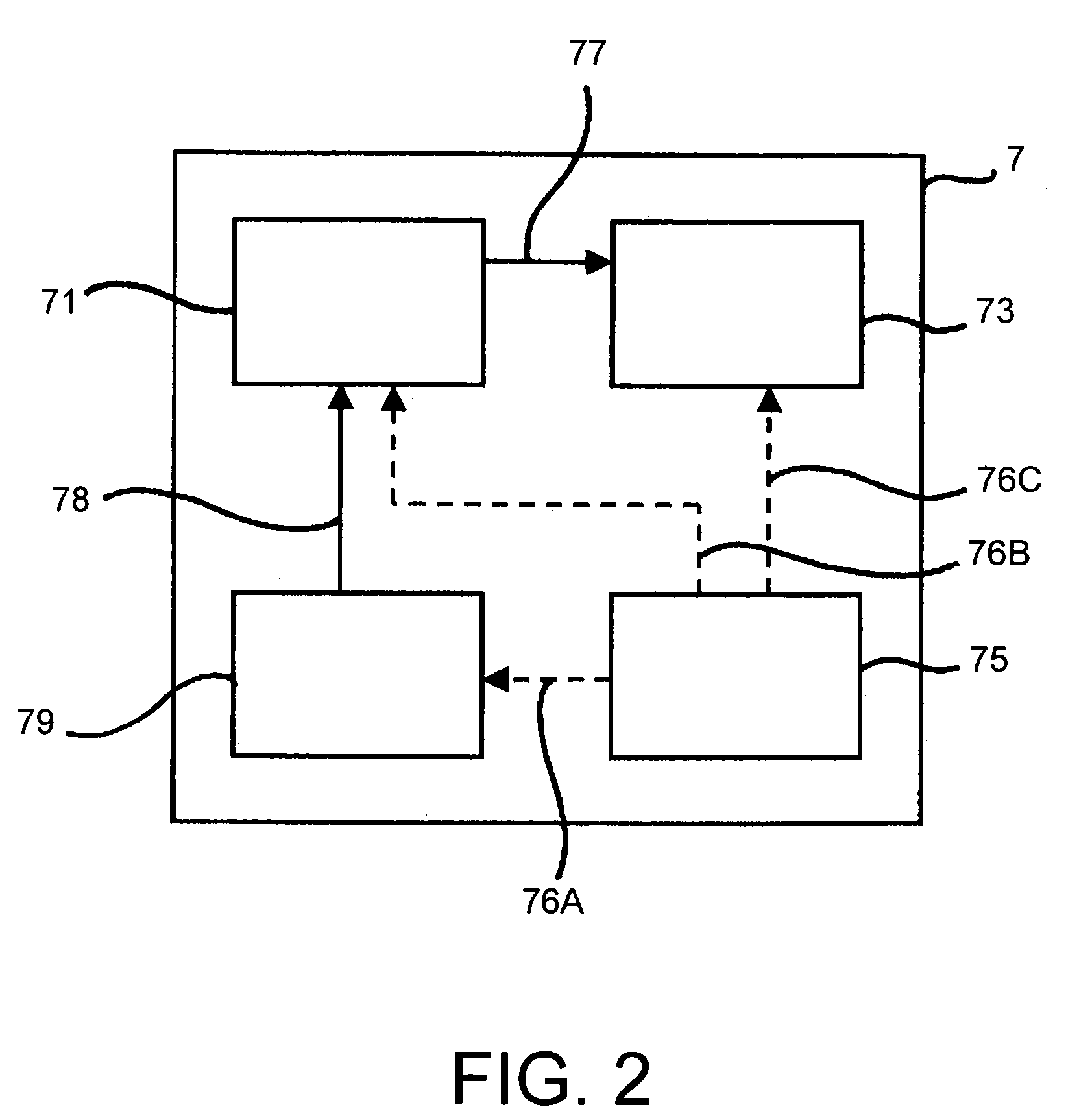
[0022]The video device 7 is shown in FIG. 2 in the form of a simplified bloc...


PUM


Abstract

An optical observation apparatus includes: an optical system which produces an image of an object being observed and a video device (7) for recording the image and producing an image signal. The video device (7) includes a first memory (71) for temporarily storing the image signal, a second memory (73) in data communication (77) with the first memory (71), and a control device (75) in communication (76A, 76B) with both memories (71, 73) for controlling the storage procedure in the first memory and data transfer from the first to the second memory. The control device (75) controls the storage procedure and the data transfer so that overwriting of such data already stored for a given period of time in the first memory (71) is effected and that transfer of the content of the first memory (71) to the second memory (73) takes place as a reaction to a trigger signal.

Description

BACKGROUND OF THE INVENTION[0001]1. Field of the Invention[0002]The invention concerns an optical observation apparatus, in particular an operation microscope, with a video device.[0003]2. Description of the Related Art[0004]Optical observation apparatuses such as for example microscopes, telescopes or endoscopes are used for example to view objects which are small, far away or which involve difficulties in access. In such an apparatus the objects are frequently reproduced by means of an optical system which in the simplest case can be an objective lens, in the form of an intermediate image on an image plane, referred to as the intermediate image plane. That intermediate image can be viewed on a magnified scale by means of an eyepiece.[0005]Often however there is a wish to subject the intermediate image to electronic analysis. In addition, it is frequently desirable for the intermediate image to be made accessible not only to a single viewer but a plurality of viewers at the same ti...

Claims


Application Information

Patent Timeline
IPC IPC(8): H04N7/18G02B21/36A61B1/04A61B19/00G02B23/18H04N5/77H04N5/781H04N5/907
CPCG02B23/18H04N5/772H04N5/907H04N5/781G02B21/22
Inventor GAIDA, GERHARDQUENDT, DIETERBRUNNER, DIRKBENNINGER, RALFMONZ, LUDWINHAISCH, MICHAEL
Owner CARL-ZEISS-STIFTUNG TRADING AS CARL ZEISS
Why Eureka
Try Eureka