Acoustic vibration analyzing apparatus and acoustic vibration analyzing method, program for analyzing acoustic vibration, and recording medium, readable by computer, on which program for analyzing acoustic vibration is stored

a technology of acoustic vibration and analyzing apparatus, which is applied in the direction of machines/engines, digital computer details, instruments, etc., can solve the problems of uneven results of sensory inspection, inability to identify the place from which abnormal sounds are generated, and difficulty in investigating the correlation between the results of sensory inspection and the actual measured results

Active Publication Date: 2008-07-15
HONDA MOTOR CO LTD
View PDF14 Cites 798 Cited by
  • Summary
  • Abstract
  • Description
  • Claims
  • Application Information

AI Technical Summary

Benefits of technology

[0013]In accordance with the acoustic vibration analyzing apparatus of the invention, since the order of sounds or vibrations is calculated, and the acoustic pressure level corresponding to the calculated order and the vehicle speed is displayed, it becomes possible to identify a source of generation of abnormal sounds and vibrations that are generated in response to changes in the vehicle speed. Further, since matching with sensory inspection can be easily carried out, it becomes easy to check generation of abnormal sounds and vibrations and to identify the source of generation thereof. In addition, since the source of generation of abnormal sounds and vibrations can be reliably identified, this contributes to reducing the number of processes of replacement work. Since the source of generation of abnormal sounds and vibrations can be identified by the order without dependency on the number of revolutions of a rotating body, the source of generation of abnormal sounds and vibrations can be controlled and distinguished even with a plurality of rotating bodies having approximately equal frequencies.
[0031]With the recording medium readable by a computer of the invention, by only causing the acoustic vibration analyzing program to be executed by a computer, acoustic vibration analysis can be carried out, and it is possible to identify the source of generation of abnormal sounds and vibrations.

Problems solved by technology

Incidentally, with conventional analyzing apparatuses, it is impossible to identify a place from which abnormal sounds being generated, if there is a plurality of rotating bodies.
Also, even if an attempt is made to identify a place at which abnormal sounds being generated by way of sensory inspection, unevenness in results of sensory inspection is liable to occur because such a inspection is based on the sensitivity of a human being, and it is difficult to investigate the correlation between the results of the sensory inspection and the actually measured results.
In particular, in a unit such as a transmission of an automobile, in which gears are disposed multi-axially on a rotating shaft, or multi-axial rotating shafts are incorporated, a number of places may be guessed to be the place where abnormal sounds are occurring, and it is difficult to identify the place of occurrence of the abnormal sounds.
In addition, with the conventional apparatuses, evaluation is carried out based on the elapsed time during a number of revolutions of a rotating body, and since the actual vehicle speed is different from the rotation speed of the rotating body when an object to be inspected such as an automobile moves, it is difficult to investigate the correlation of the results measured.
Further, in judgment based on maximum value as in the analyzing apparatus described in Japanese Published Examined Patent Application No. 2596081, if the volume of the abnormal sounds is low, it is not possible to detect the frequency even if it can be sensed by a human being.

Method used


Image

  • Acoustic vibration analyzing apparatus and acoustic vibration analyzing method, program for analyzing acoustic vibration, and recording medium, readable by computer, on which program for analyzing acoustic vibration is stored
  • Acoustic vibration analyzing apparatus and acoustic vibration analyzing method, program for analyzing acoustic vibration, and recording medium, readable by computer, on which program for analyzing acoustic vibration is stored
  • Acoustic vibration analyzing apparatus and acoustic vibration analyzing method, program for analyzing acoustic vibration, and recording medium, readable by computer, on which program for analyzing acoustic vibration is stored

Examples


Embodiment Construction

[0040]A detailed description is given of an embodiment of the invention with reference to the drawings.

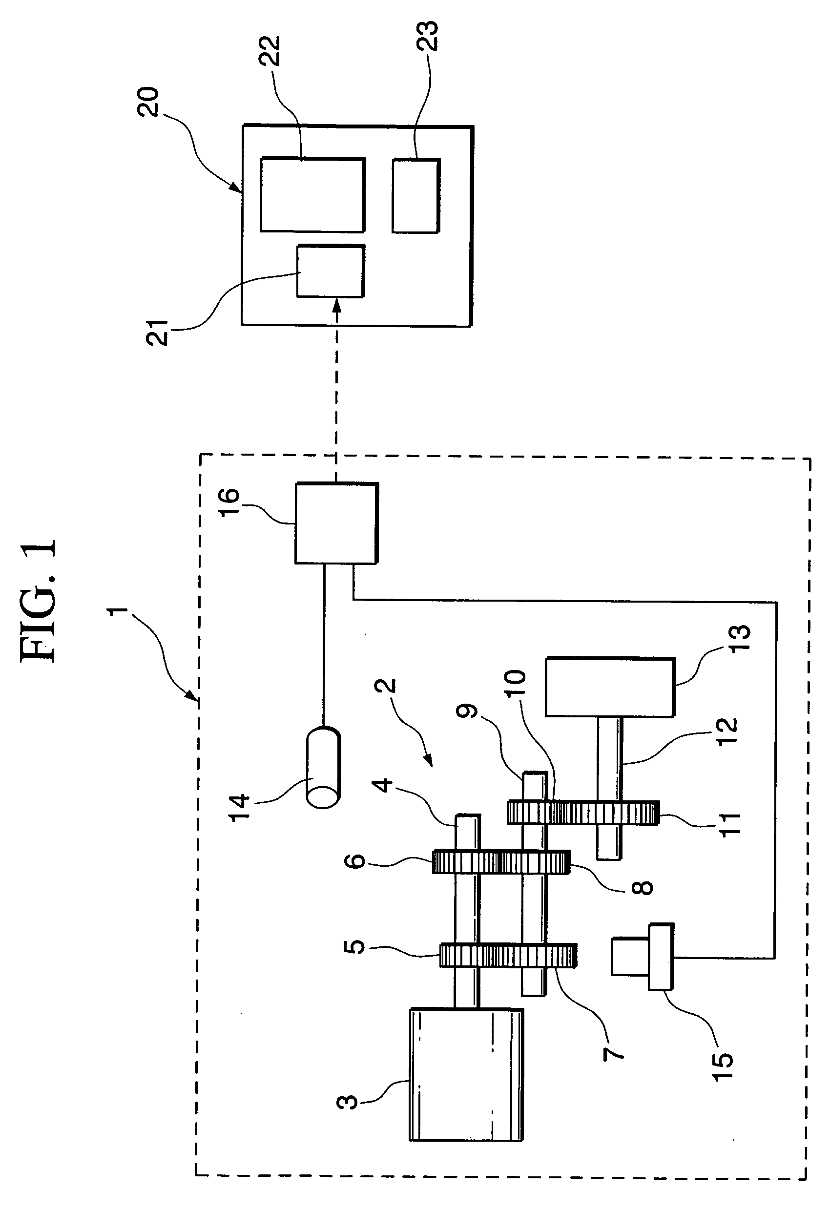
[0041]First, a description is given of an object to be inspected according to the embodiment. As depicted in FIG. 1, the object to be inspected by the embodiment is a vehicle 1, in further detail, a transmission 2 of the vehicle.

[0042]The transmission 2 has a first shaft 4 driven and rotated by using an engine 3 as a drive source. A first-speed drive gear 5 having ten teeth and a second-speed drive gear 6 having fifteen teeth are attached to the first shaft 4 in parallel. A first-speed driven gear (rotating body) 7 having twenty teeth is engaged with the first-speed drive gear 5, and a second-speed driven gear 8 having five teeth is engaged with the second-speed drive gear 6. Both of the first-speed driven gear 7 and the second-speed driven gear 8 are attached to a second shaft 9.

[0043]A final drive gear 10 having ten teeth is attached to the second shaft 9. The final drive gear 10...


PUM


Abstract

The present invention provides an acoustic vibration analyzing apparatus for carrying out acoustic vibration analysis by picking up data of sounds generated due to rotation of a plurality of gears and data of the number of revolutions of a gear selected from a plurality of gears when a transmission of a vehicle having the plurality of gears operates. The acoustic vibration analyzing apparatus comprises an acoustic vibration calculation portion for analyzing acoustic data in terms of frequency, an order calculation portion for calculating an order in compliance with the specifications of a plurality of gears, a speed calculation portion for calculating the speed of a vehicle, and a display unit for displaying acoustic pressure levels with the order and vehicle speed associated therewith.

Description

TECHNICAL FIELD[0001]The present invention relates to an apparatus for analyzing sound or vibration generated due to rotation of a rotating body, and in particular, to an apparatus and a method of analyzing abnormal sounds by investigating the correlation between sensory inspection carried out while causing a vehicle to actually run, and gear sounds generated from a transmission, a program used therefor, and a recording medium, readable by a computer, in which the program is stored.[0002]The present application is based on the priority of Japanese Patent Application No. 2003-209353 filed on Aug. 28, 2003, and Japanese Patent Application No. 2004-194413 filed on Jun. 30, 2004, the contents of which are incorporated herein by reference.BACKGROUND ART[0003]As an apparatus equipped with a rotating body such as a gear is run, there are cases in which continuous sounds continuously generated regardless of running state, non-continuous sounds generated in a particular running state, and vi...

Claims


Application Information

Patent Timeline
Patent Type & Authority Patents(United States)
IPC IPC(8): G01P3/00G01H1/00G01H3/00G01H17/00G01M13/02G01M17/007
CPCG01M13/028G01H1/003
Inventor NAKAMURA, TAKAAKI
Owner HONDA MOTOR CO LTD
Why Eureka
Try Eureka