Suspension system for a row crop planter unit

Active Publication Date: 2008-07-22
KURZ CLARE D
View PDF14 Cites 42 Cited by
  • Summary
  • Abstract
  • Description
  • Claims
  • Application Information

AI Technical Summary

Benefits of technology

[0016]Still another object of the invention is to provide a suspension system fo

Problems solved by technology

As the planter is pulled through the field, the planter units tend to bounce upwardly and downwardly due to encountering uneven terrain.
If the planter unit does objectionably bounce, the seed spacing and seed depth of the pla

Method used


Image

  • Suspension system for a row crop planter unit
  • Suspension system for a row crop planter unit
  • Suspension system for a row crop planter unit

Examples


Example

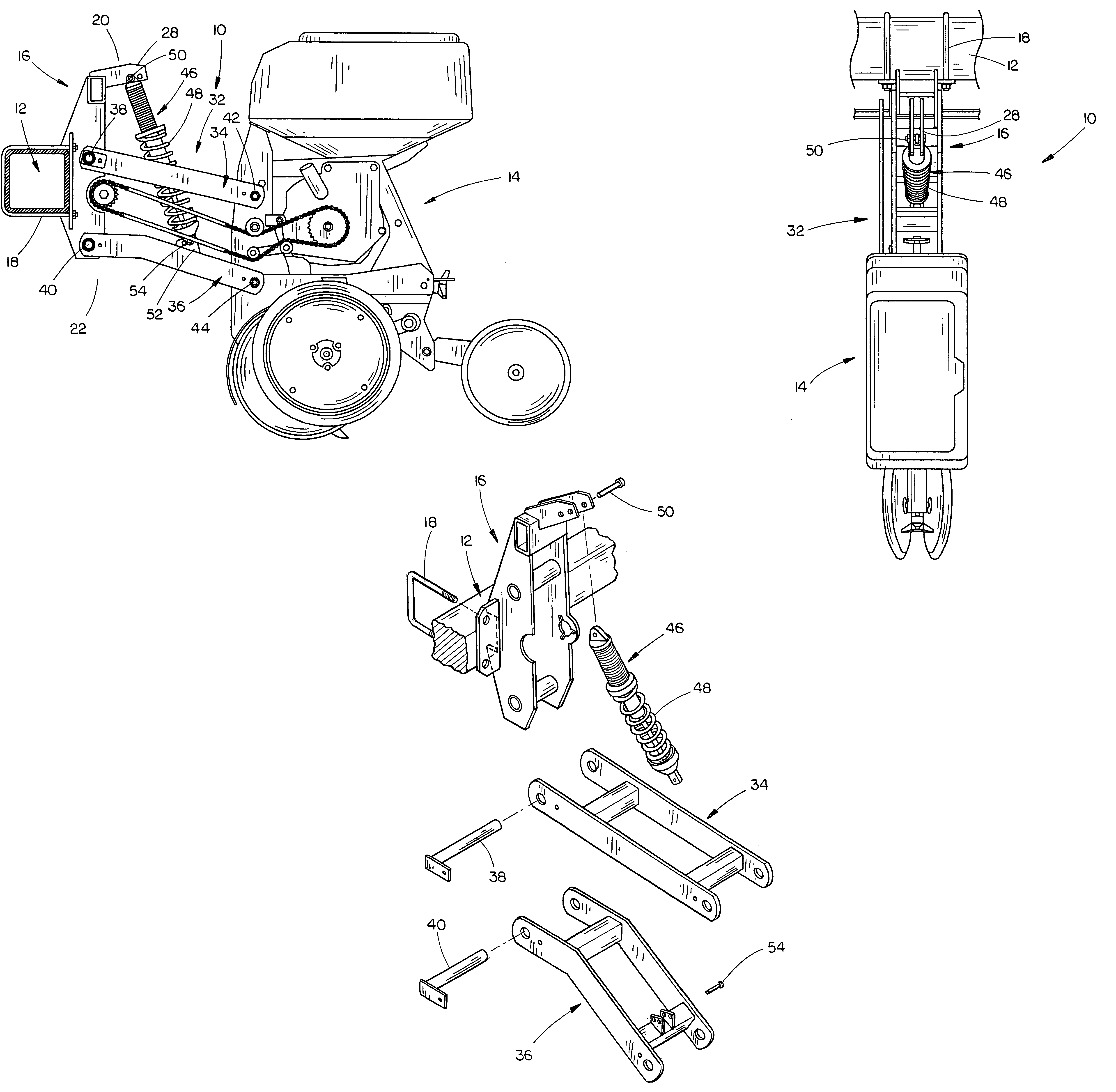
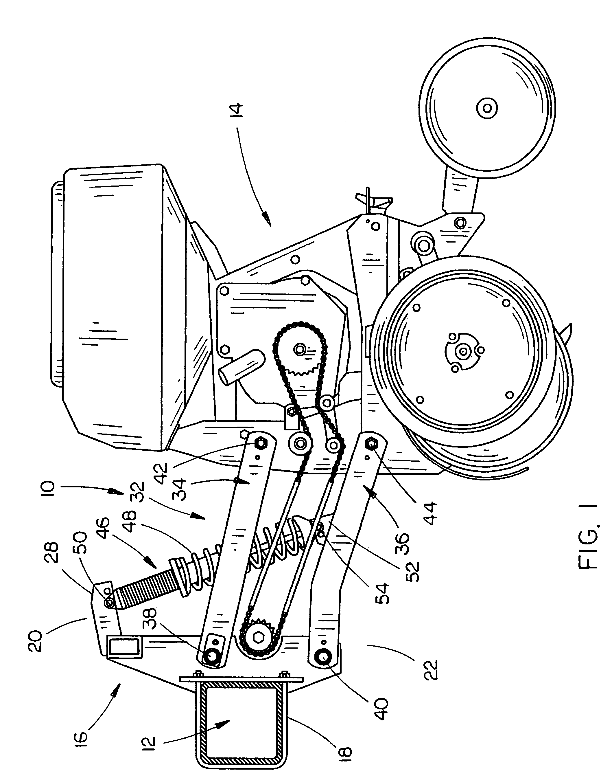
[0029]The numeral 10 refers generally to a row planter which may be either a single row planter or a twin row planter. A twin row planter is disclosed in U.S. Pat. No. 6,520,100. Planter 10 generally includes a toolbar or frame 12 and planter units 14 which include conventional furrow opening discs, depth gauge wheels, furrow closing discs, compaction wheel, etc.

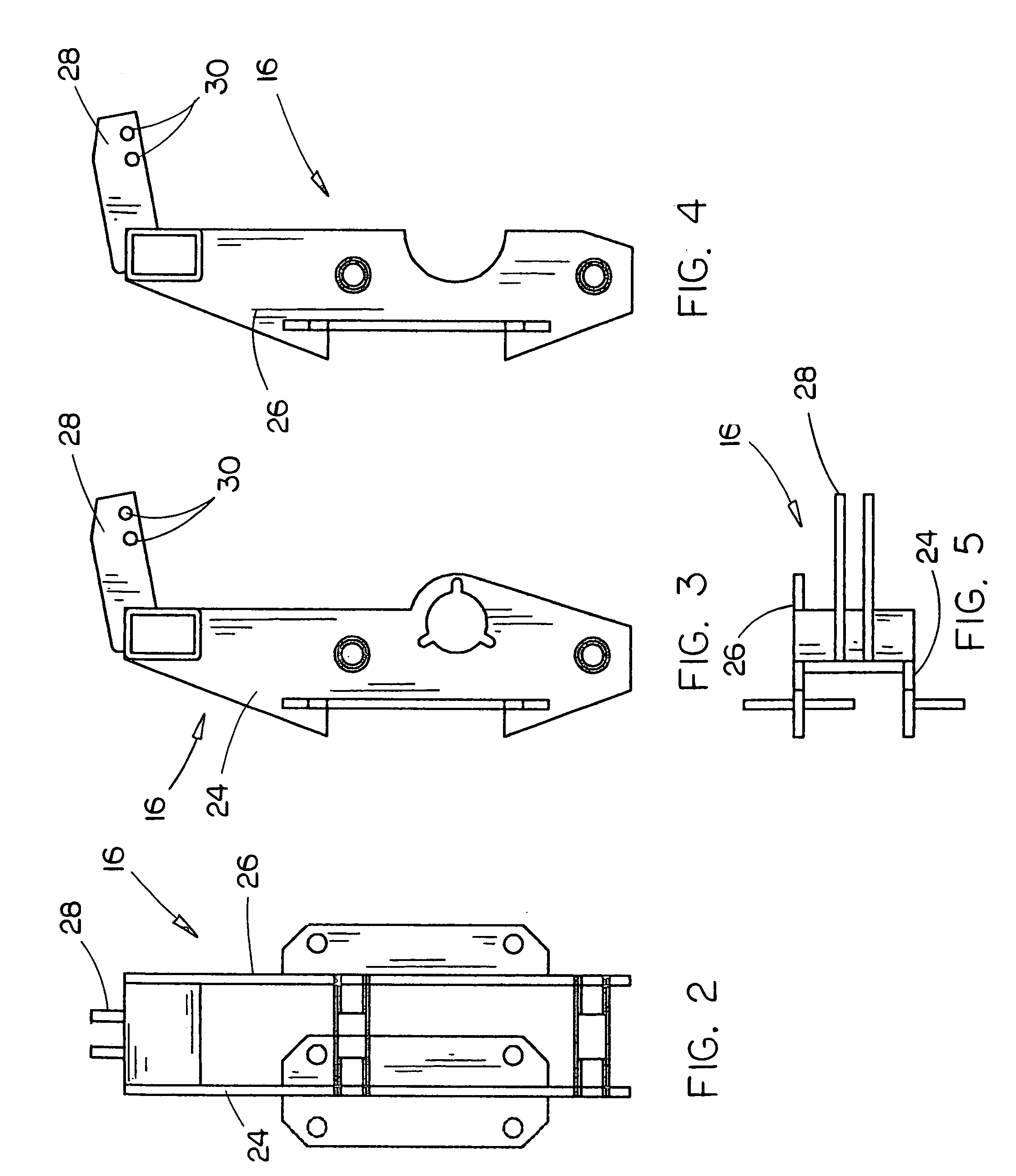
[0030]A plurality of horizontally spaced-apart mounting brackets 16 are secured to the toolbar 12 in conventional fashion such as by U-bolts 18 or the like. Mounting bracket 16 includes an upper end 20 and a lower end 22. Mounting bracket 16 includes spaced-apart side plates 24 and 26 which have a rearwardly extending arm assembly 28 at their upper ends. Arm assembly 28 may have a plurality of adjustment openings 30 formed therein.

[0031]Each of the planter units 14 is pivotally secured to a mounting bracket 16 by a parallel arm linkage 32 which includes an upper pair 34 of parallel arms and a lower pair 36 of parallel arms. ...


PUM


Abstract

A suspension system for a row crop planter unit which includes a shock absorber extending between the planter unit mounting bracket and the parallel arm linkage which vertically mounts the planter unit to a toolbar. The shock absorber permits the planter unit to move more quickly in the rebound cycle than in the compression cycle to reduce row unit bounce.

Description

CROSS-REFERENCE TO RELATED APPLICATION[0001]This application claims the benefit of U.S. Provisional Application Ser. No. 60 / 964,920 entitled “SUSPENSION SYSTEM FOR A ROW CROP PLANTER UNIT” filed Aug. 16, 2007, the disclosure of which is hereby incorporated herein by reference.BACKGROUND OF THE INVENTION[0002]1. Field of the Invention[0003]This invention relates to a suspension system for a row crop planter unit and more particularly to a suspension system preferably in the form of a coil-over shock absorber which is operatively connected to the supporting frame of the planter unit and to the parallel arm linkage of the row crop planter unit to reduce row unit bounce (R.U.B.).[0004]2. Description of the Related Art[0005]Many types of suspension systems or mounting systems for row crop planter units have been previously provided. In most instances, the row crop planter units are connected to a transversely extending toolbar in a horizontally spaced-apart manner for single row planting...

Claims


Application Information

Patent Timeline
IPC IPC(8): A01C5/00A01C7/18
CPCA01C7/205Y10S111/926Y10S111/927
Inventor KURZ, CLARE D.
Owner KURZ CLARE D
Why Eureka
Try Eureka