
Apparatus and method for drilling a branch borehole from an oil well

a branch borehole and oil well technology, applied in the direction of borehole/well accessories, directional drilling, water installations, etc., can solve the problems of lack of lateral branch boreholes at a selected depth from a main well, lack of a system for drilling an elongated,

Inactive Publication Date: 2008-07-22
SCHLUMBERGER TECH CORP
View PDF37 Cites 34 Cited by
  • Summary
  • Abstract
  • Description
  • Claims
  • Application Information

AI Technical Summary

Benefits of technology

The invention provides an articulated modular drill train for drilling through the wall of an oil well and into earth formation to make a branch borehole at a selected depth. The drill train includes a drill module, a first self-propelled thrust module, a second self-propelled thrust module, and a cuttings removal module. The drill module has a forward cutting portion and a pivotal cutting portion covering the sides of the drill module. The thrust modules each have at least two extendible thrusters and an anti-rotation device. The drill train also includes a mechanical articulated linkage, a screw-type cuttings removal module, and a method for drilling through the wall of an oil well and into earth formation to make a branch borehole. The technical effects of the invention include improved drilling efficiency, reduced cuttings removal time, and improved wellbore stability.

Problems solved by technology

The oil well drilling industry lacks a system for drilling an elongated, small diameter, lateral branch borehole at a selected depth from a main well, where the lateral branch borehole extends a significant distance from the main well, and the transition from main well to branch borehole has a very small radius of curvature.
Currently available systems for drilling lateral branch boreholes at a selected depth from a main well do not provide this combination of capabilities.

Method used


Image

  • Apparatus and method for drilling a branch borehole from an oil well
  • Apparatus and method for drilling a branch borehole from an oil well
  • Apparatus and method for drilling a branch borehole from an oil well

Examples


Embodiment Construction

Detailed Description General

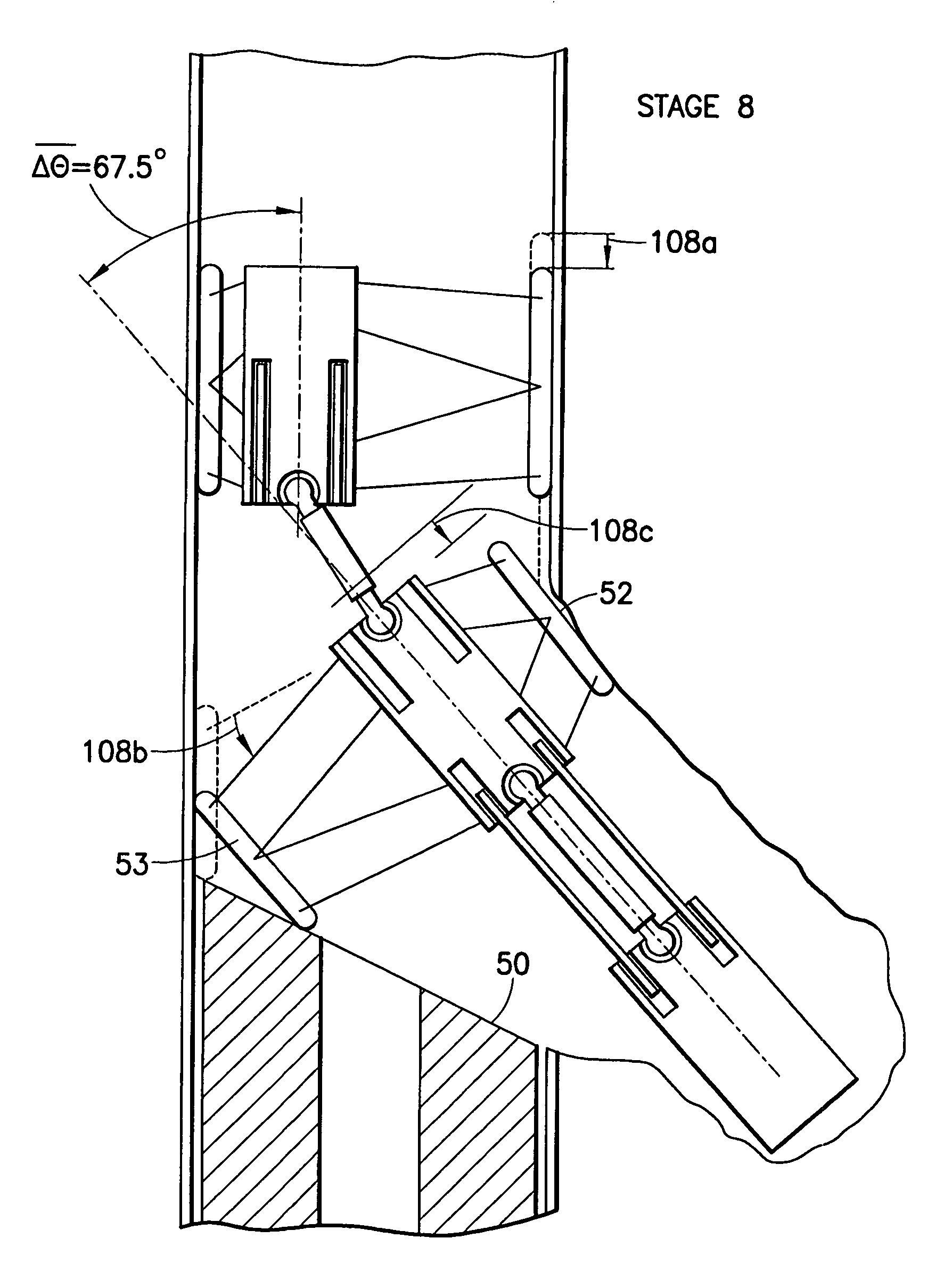
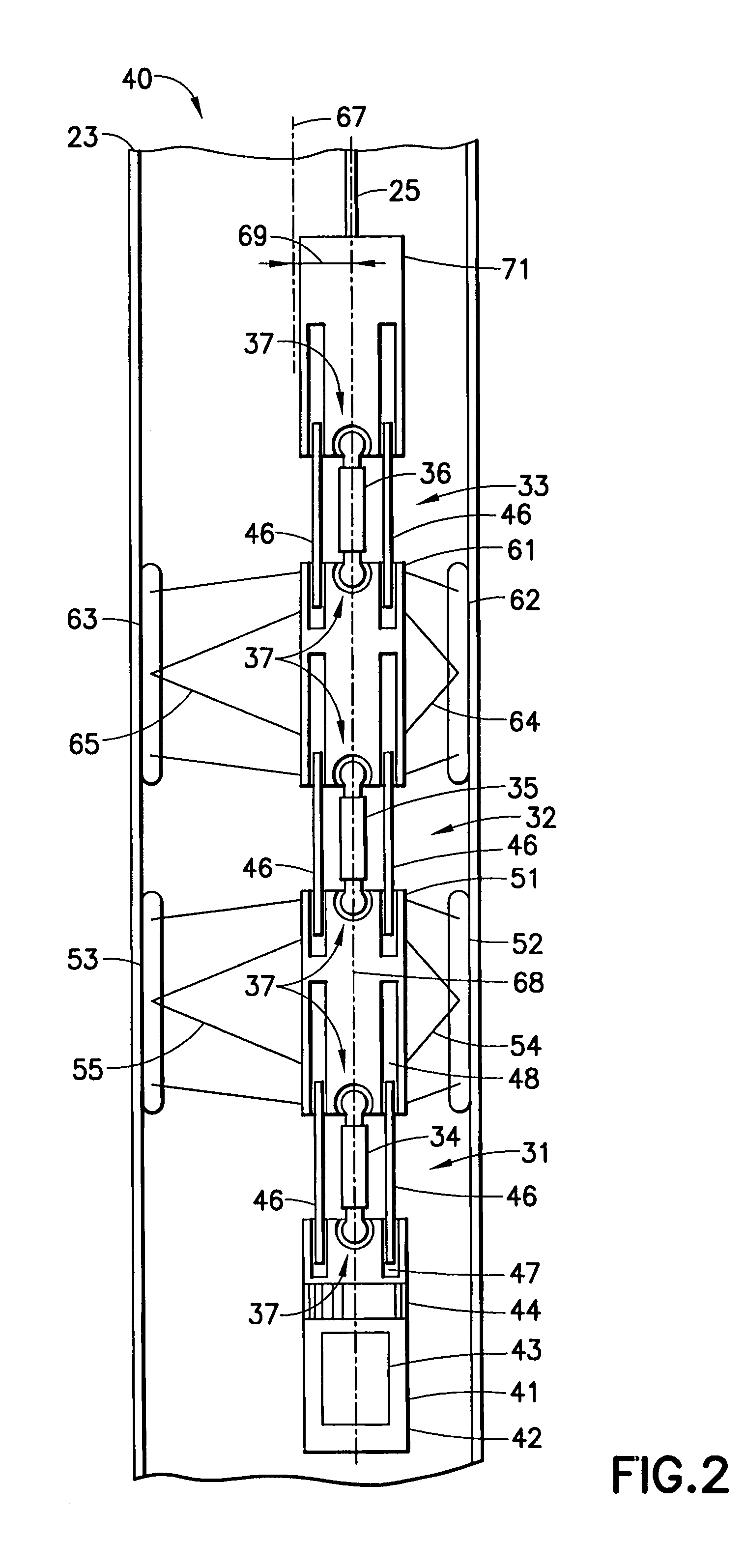
[0057]The present invention provides an apparatus and method for drilling through the casing of an oil well into earth formation at a selected depth to make a branch borehole. The apparatus includes an articulated modular drill train attached to a wireline. A first preferred embodiment of the apparatus of the invention is illustrated in FIGS. 1-19. A first preferred method of the invention is illustrated in FIGS. 20-29.

Detailed Description, Apparatus of First Preferred Embodiment

The Modules of the Drill Train

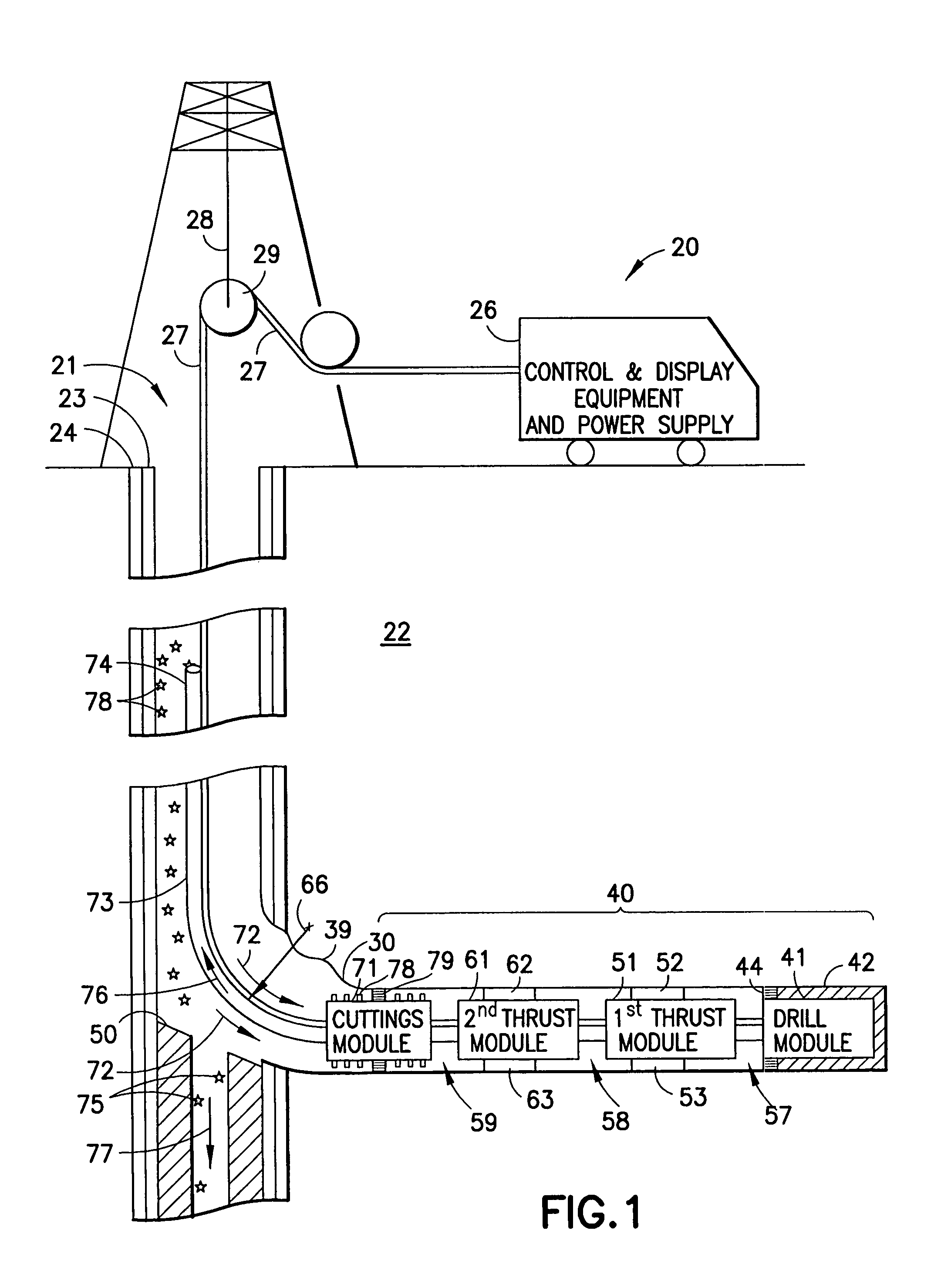
[0058]FIG. 1 is a cut-away schematic view of the first preferred embodiment of apparatus for drilling a branch borehole from an oil well according to the invention. FIG. 1 shows branch borehole drilling system 20 located in branch borehole 30 that has been drilled from cased well 21 within earth formation 22. Cased well 21 is a typical main borehole encased by a steel casing 23 having an internal diameter of approximately 15 cm. Casing 23 is backed by...


PUM


Abstract

A wireline drill train is used to drill an elongated, small diameter, lateral branch borehole from near the base of a main well. The drill train, includes a drill module, a first self-propelled thrust module coupled to the drill module, and a second self-propelled thrust module pivotally coupled to the first self-propelled thrust module. Each thrust module includes at least two extendible thrusters. Each extendible thruster includes a six-bar mechanism and a traction tread. The drill train further includes a first articulated linkage linking the first self-propelled thrust module to the drill module, and a second articulated linkage linking the second thrust module to the first thrust module. The second articulated linkage includes a thrust-transmission bar and three retractable stiffener bars. The method for drilling the curved transition region of the lateral branch borehole includes executing a series of alternating pivotal drilling steps and forward drilling steps to create a step-cut region of branch borehole having very small radius of curvature.

Description

TECHNICAL FIELD[0001]This invention relates generally to drilling systems for oil wells.BACKGROUND OF THE INVENTION[0002]The oil well drilling industry lacks a system for drilling an elongated, small diameter, lateral branch borehole at a selected depth from a main well, where the lateral branch borehole extends a significant distance from the main well, and the transition from main well to branch borehole has a very small radius of curvature. For a typical main well having an internal diameter of approximately 15 cm, a suitable system would drill a branch borehole having a curved transition portion with radius of curvature less than 5 meters, and would then drill a lateral branch borehole, having a diameter of approximately 60 mm, for a distance of approximately 100 meters. Currently available systems for drilling lateral branch boreholes at a selected depth from a main well do not provide this combination of capabilities. A system having this combination of capabilities would be v...

Claims


Application Information

Patent Timeline
Patent Type & Authority Patents(United States)
IPC IPC(8): E21B23/00E21B7/06E21B29/06
CPCE21B7/06E21B29/06E21B21/00E21B2023/008E21B23/001E21B7/067E21B4/18E21B7/061
Inventor GUERRERO, JULIO C.PAFITIS, DEMOSARZOUMANIDIS, ALEX
Owner SCHLUMBERGER TECH CORP
Learn More