[0011]A
system of bendable plates is provided that may be easily and safely reconfigured inside the patient's body (in situ) during the surgical procedure. The system can be reconfigured without distorting the shape of bone fastener holes in the plate, and any threads within the holes. The system includes and is adapted for use with in situ bending tools to reconfigure the plate inside the patient's body during the surgical procedure.
[0013]An elbow fracture fixation system is provided that also includes locking fasteners for attachment of the bone plate to the
fractured bone. In general, the primary functions of various
bone plates of the system (which are all adjacent near the elbow joint) include not only holding the bone fragments together in healing alignment, but also the transfer of forces from the
metaphysis to the
diaphysis of the fractured bone while the bone is mending. The system allows the distal tip of a fastener to be anchored into healthy,
cortical bone, and the transfer of force from the healthy bone to the plate, such that the plate properly accomplishes
load sharing.
[0019]According to another aspect of the system,
bone plates for the lateral and medial surfaces of the distal
humerus each have a
rigid body portion with substantially the same thickness. The rigid portion of each of the medial and lateral plates has a distal end, a proximal end, a top surface, a bottom surface, a medial edge and an opposing lateral edge. The plates also have a plurality of holes extending between the top and bottom surfaces, each of the holes for receiving a fastener for attachment of the bone plate to the bone. The lateral bone plate also has at least one positioning foot extending from an edge downwardly towards the
bone surface to aid in the positioning of the bone plate on the
bone surface.
[0021]According to another aspect of the system, a bone plate for the posterolateral surface of the distal humerus has a body with a thickness substantially greater than the medial plate (greater than fifty percent thicker). The body has a proximal end, a distal end and a curvilinear, longitudinal axis extending therebetween. A first arm and a second arm extend from proximal end on opposing sides of the longitudinal axis, thereby forming a Y-shape, and a third arm extends transversely away from the longitudinal axis to extend partially around the lateral side of the distal humerus. The first, second, and third arms each includes a
ring element having a hole and are attached to the body by respective bendable bridge elements. The body includes threaded holes and an elongated slot, each of which may be located along the longitudinal axis. The slot may be configured to receive a compression fastener. Each of threaded holes is configured for receiving one of the fasteners. The threaded holes may be preassembled with a plurality of
drill guides, with a proximal hole receiving a short
drill guide. In the same manner as with the lateral and medial plates, the surgeon may closely match the shape of posterolateral plate to the
bone surface and redirect the trajectories of the fasteners to capture bone fragments and avoid fracture lines and other fasteners.
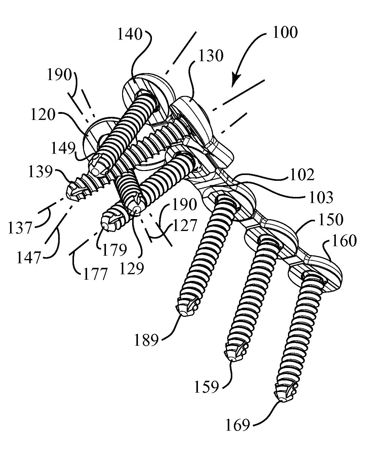
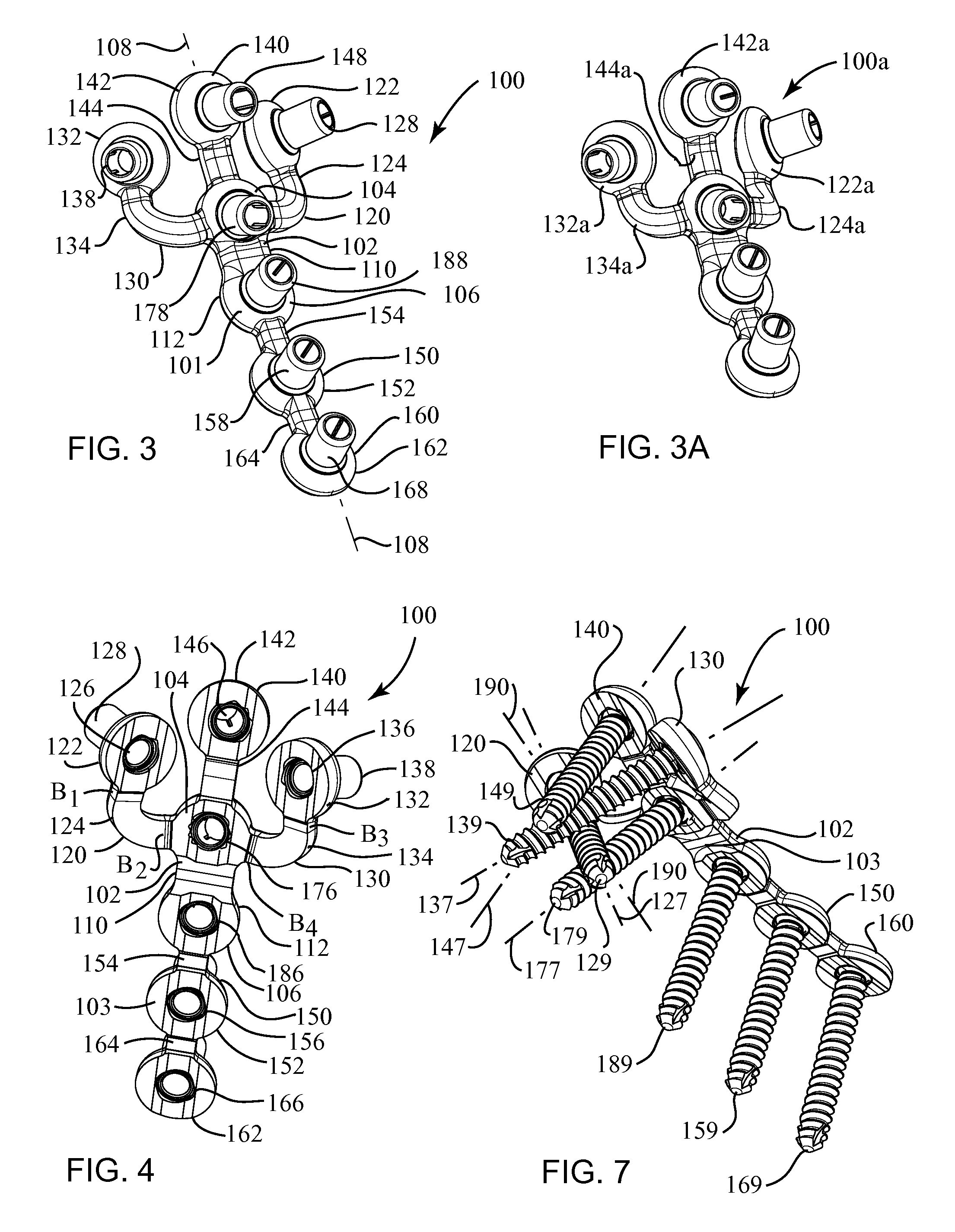
[0024]Still referring to the bone plate for the coronoid, the plurality of arms may include a first arm extending distally from the central
ring element, a second arm extending medially from the central
ring element and a third arm extending laterally from the central ring element. The first arm may have three of the plurality of ring elements spaced apart and arranged linearly, and the second arm may have one of the plurality of ring elements, and the third arm may have one of the plurality of ring elements. The bone plate may also have a
buttress element attached to one of the plurality of ring elements by a bendable web element, and the bendable web element is reconfigurable in situ such that the
buttress element can bear against the bone surface. The
buttress element may extend proximally from the central ring element. The buttress element also may extend medially from the ring element of the second arm. The bone plate may also have a plurality of
drill guides, and each of the ring elements is preassembled with one of the drill guides. The drill guides may be removably attachable to a bending tool, such that a user may use a pair of bending tools to apply a leveraging force to reconfigure, in situ, each of the first, second and third arms.
[0029]According to another aspect of the system, the system has a bone plate having a threaded hole defining a thread axis for receiving a
fixed angle, locking fastener. The system also has a
drill guide preassembled into the threaded hole, the
drill guide including a
drill guide bore sized to guide a bone drill. The system also has an
insertion tool having a cylindrical body with distal and proximal ends and a longitudinal axis extending therebetween. The cylindrical body has a grip surface for holding the
insertion tool during use. The cylindrical body also has a longitudinal bore extending between the distal and proximal ends and sized for guiding a K-wire, and the distal end is configured to be removably attached to the drill guide so that the longitudinal bore aligns with the thread axis. The distal end of the
insertion tool may also fit securely into the drill guide, such that the user may use the cylindrical body as a
handle to manipulate the bone plate during the surgical procedure.


