Umbilical cord clamp and cutter

a technology of umbilical cord and cutter, which is applied in the field of umbilical cord clamps and cutters, can solve the problems of unaesthetically attractive hollister clamps, increased overall procedure costs, and increased risk of blood-borne pathogens for hospital personnel, so as to prevent blood splatter, easy and safe operation with one hand

Inactive Publication Date: 2008-07-22
THE UTOPIA GRP
View PDF36 Cites 41 Cited by
  • Summary
  • Abstract
  • Description
  • Claims
  • Application Information

AI Technical Summary

Benefits of technology

[0014]As the umbilical cord is severed as described above, the shells substantially surround the cord and thereby prevent the splattering of blood. Preferably, the clamping member in the first shell has at least one tab for engagement with a catch extending from the second shell. More preferably, two tabs are provided for engagement with the catch. Together, the tabs and catch constitute a latch to keep the shells closed after the cut is complete. Toward the end of the closing of the shells, the first tab clicks into engagement with the catch to indicate that the shells are prevented from reopening. Upon further squeezing of the shells, the second tab clicks into engagement with the catch to indicate that the cut is complete. Also, each shell is preferably provided with a guide that engages the guide of the other shell to form a detent that holds the shells in a partially open initial position before the cutting process is begun. The exterior of each shell is preferably provided with a plurality of protrusions or recesses to assist the user in gripping the cutter. Together, the shells have an overall outer shape that comfortably fits in the palm of the user's hand.
[0015]In the vicinity where the removable clamp is mounted to the shells of the cutter, the periphery of each shell is provided with an indentation to allow access to a protrusion of the removable clamp. After the umbilical cord is severed, the user may use a thumb to apply a force to the protrusion of the removable clamp in order to dislodge the removable clamp from the shells. The removable clamp is then left with the baby, and the cutter is discarded with the placenta. The removable clamp is preferably shaped like the head of a koala bear, with facial indicia (e.g., eyes, nose, and mouth) on the face. When the removable clamp is engaged with the shells of the cutter, the face of the koala bear is toward the interior of the cutter. After the removable clamp is removed from the cutter, the baby is left with a clamp on its navel that resembles a koala bear, which is much more attractive than a Hollister clamp. Therefore, the removable clamp of the present invention is aesthetically pleasing as well as very practical. The removable clamp may also be made in the shape of various other animals, such as a teddy bear or duck, or other non-animal shapes, such as an ellipse.
[0016]In addition, the removable clamp is preferably provided with a recess on the back side of the clamp body. The recess provides for reduced weight of the clamp and tends to eliminate sink marks if the clamp is manufactured by a molding process. Also, the recess allows for a wireless transmitter to be inserted in the clamp so that the baby can be tracked electronically.
[0018]It is a further object of the present invention to provide a disposable umbilical cord clamp and cutter that prevents the splatter of blood or other fluids when cutting an umbilical cord.
[0019]It is another object of this invention to provide a combined umbilical cord clamp and cutter that is easily and safely operable with one hand.
[0020]It is still another object of this invention to provide an improved umbilical cord clamp that is aesthetically pleasing.

Problems solved by technology

First, it takes three separate instruments (two clamps and a cutting tool) to accomplish the process of cutting the umbilical cord using the Hollister clamp.
If a hemostat is used instead of a second Hollister clamp during the cutting process, the overall procedure is even more cumbersome because the hemostat is typically replaced with a second Hollister clamp after the cord is cut, which adds a fourth instrument.
Second, the Hollister clamp does not provide any shield from the splatter of blood when the umbilical cord is cut, which presents a danger of blood-borne pathogens to hospital personnel.
Additionally, the Hollister clamp is not aesthetically attractive when left on the baby's navel.
Although the Simmons device combines the two clamps and cutter into a single tool, it does not solve the problem of the need for a shield to guard against the splatter of blood nor the problem of poor aesthetics.
Again, however, the Jensen device does not have a shield to prevent the splatter of blood, and the clamps are modifications of the Hollister clamp which are not aesthetically appealing.
Although the Watson device solved the blood splatter problem, the pair of semi-cylinders left with the baby is bulky and aesthetically unattractive.
Additionally, although the Watson device was intended to enable one-handed operation, the Watson device presents significant difficulties in the process of depressing the blade and breaking the clamps apart.
As is known in the art, in multi-infant births (i.e., twins, triplets, quadruplets, and so on), the umbilical cords of the various infants are frequently tangled up, sometimes severely so, which makes keeping track of the cord (and placenta) associated with each infant a tedious and time consuming task for delivery personnel.
This identification process takes precious time, which is of particular concern because multi-infant births are typically carried out by Cesarean section.
In a Cesarean section operation, the risk of complications increases as the duration of the operation increases.

Method used


Image

  • Umbilical cord clamp and cutter
  • Umbilical cord clamp and cutter
  • Umbilical cord clamp and cutter

Examples


Embodiment Construction

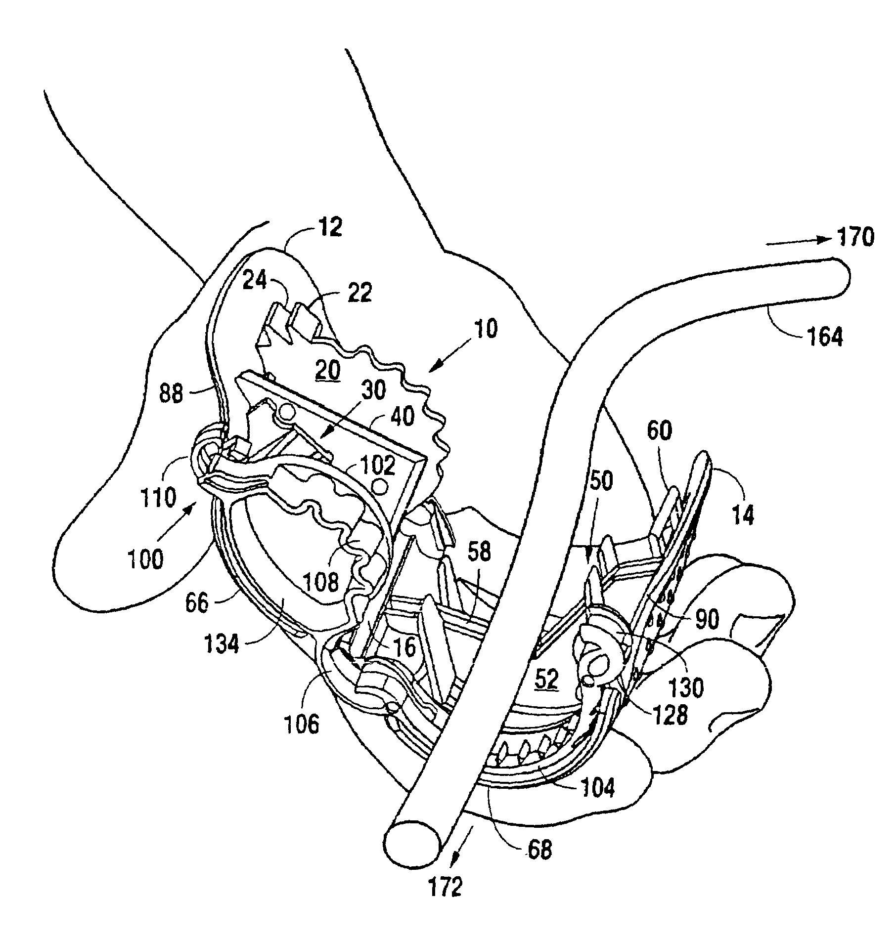
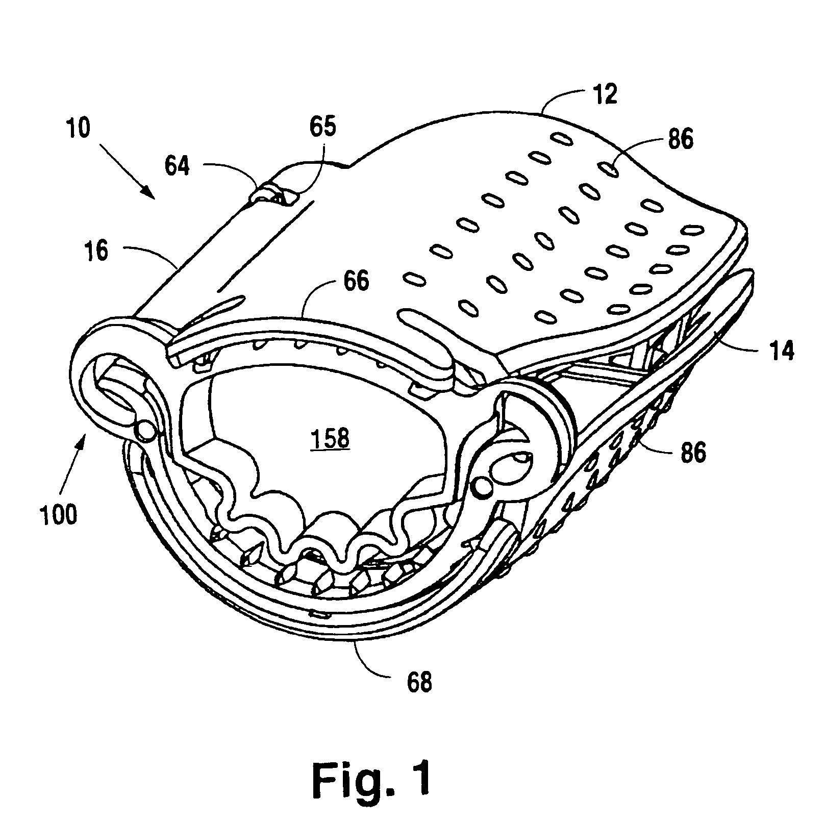
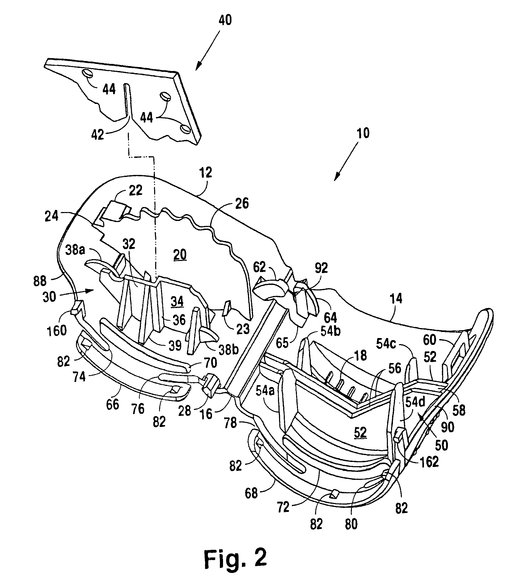
[0083]Referring primarily to FIGS. 1-6, a cutter 10 in accordance with the present invention comprises a first shell 12 joined to a second shell 14 by a longitudinal hinge 16. Preferably, hinge 16 is integral with shells 12 and 14, but shells 12 and 14 could be made separately and joined with a separate hinge. As discussed further below, a removable baby clamp 100 is installed on one end of cutter 10. Baby clamp 100 is not shown in FIGS. 2, 3, and 6 for the sake of clarity. A blade 40 is transversely mounted to the inside of shell 12 with a blade holder 30, which extends from the inner surface of shell 12. Blade 40, which is preferably made of surgical steel about 0.03 in. thick, is not shown in FIGS. 4 and 5 for the sake of clarity. The end of cutter 10 to which baby clamp 100 is mounted is referred to as the “baby end,” and the other end is referred to as the “mother end.” As best seen in FIG. 2, blade holder 30 preferably comprises two upstanding walls 32 and 34 connected by a su...


PUM


Abstract

A novel umbilical cord clamp and a combined umbilical cord clamp and cutter are provided for clamping and cutting umbilical cords in one motion. The cutter comprises two shells joined by a longitudinal hinge. A transverse blade is mounted in one shell, and a cutting support is mounted in the other shell across from the blade. One or more removable clamps may be engaged with the shells to be removable from the shells after cutting. Alternatively, a self-winding or plastically deformable band may be engageable with the shells. The cutter and its associated removable clamp(s) may be coordinated with an identifier, such as a color, number, or letter. Blood sampling and diagnostic features may be included with the cutter. The removable clamps may have an openable closure.

Description

CROSS-REFERENCE TO RELATED APPLICATIONS[0001]This application is a continuation-in-part of U.S. patent application Ser. No. 10 / 232,029 filed Aug. 30, 2002, now U.S. Pat. No. 6,740,095, which is a continuation of U.S. patent application Ser. No. 09 / 874,770 filed Jun. 5, 2001, now U.S. Pat. No. 6,443,958, each of which is incorporated herein by reference. This application also claims the benefit of U.S. Provisional Patent Application No. 60 / 424,776 filed Nov. 8, 2002, which is incorporated herein by reference.BACKGROUND OF THE INVENTION[0002]1. Field of the Invention[0003]This invention relates generally to umbilical cord clamps and cutters, and more particularly to a combined umbilical cord clamp and cutter for clamping and cutting an umbilical cord in one continuous motion.[0004]2. Description of the Related Art[0005]A number of clamps and cutters are known in the art for clamping and cutting the umbilical cords of newborn babies. Perhaps the most common clamp currently used for suc...

Claims


Application Information

Patent Timeline
Patent Type & Authority Patents(United States)
IPC IPC(8): A61B17/42A61B17/46A61D1/10A61BA61B1/00A61B10/00A61B17/122A61B17/32A61B19/00
CPCA61B17/128A61B17/32A61B17/122A61B10/0045A61B10/0096A61B2019/444A61B90/92A61B5/150038
Inventor WATSON, JR., RICHARD L.HICKS, RONALD B.BADER, CARRIE D. M.LEUNG, PHILIP C. Y.VILLARREAL, HECTOR C.
Owner THE UTOPIA GRP
Why Eureka
Try Eureka