Triangular wave generation circuit

a generation circuit and triangular wave technology, applied in the direction of ignition automatic control, pulse technique, instruments, etc., can solve the problems of enlarged circuit area, distorted waveform of output voltage vout, and problem of larger current consumption, so as to achieve the effect of further improving the waveform of triangular wav

Inactive Publication Date: 2008-07-22
ROHM CO LTD
View PDF3 Cites 24 Cited by
  • Summary
  • Abstract
  • Description
  • Claims
  • Application Information

AI Technical Summary

Benefits of technology

[0015]According to this embodiment, since one end of the third constant-current source is connected to the second capacitor, it doesn't open and it is fixed to a potential determined by the charge amount stored in the second capacitance. As a result, when the first switch turns on and the second terminal of the first capacitor is connected with the second terminal of the second capacitor, the precipitous drop of the output voltage is prevented and therefore a triangular wave voltage whose waveform has less distortion can be generated.
[0017]In this case, if the ratio “1” is denoted by Ic, both the first capacitor and the second capacitor are charged by the current Ic during a charge period. In a discharge period, the combined capacitor of the first capacitor and the second capacitor will be discharged at 2Ic. Since the capacitance value of the first capacitor is equal to that of the second capacitor, these two capacitors vary in the same manner. As a result, the property that the first capacitor and the second capacitor are mutually compatible and consistent in terms of the voltage variation can be enhanced and therefore the waveform of triangular wave can be further improved.

Problems solved by technology

As described above, the conventional triangular wave generation circuit 50 has a problem that the waveform of the output voltage Vout gets distorted at the time of a charge state switching to a discharge state.
This problem can be solved to a certain degree by using a capacitor CT of a larger capacitance, but this brings on another problem of an enlarged circuit area.
Moreover, the use of a larger capacitance, which requires the use of larger constant current for charging and discharging, brings about a problem of larger current consumption.

Method used


Image

  • Triangular wave generation circuit
  • Triangular wave generation circuit
  • Triangular wave generation circuit

Examples


Embodiment Construction

[0031]The invention will now be described based on preferred embodiments which do not intend to limit the scope of the present invention but exemplify the invention. All of the features and the combinations thereof described in the embodiment are not necessarily essential to the invention.

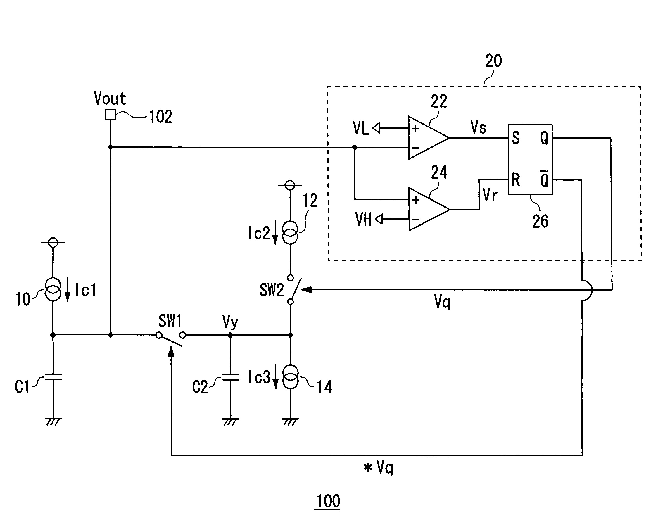
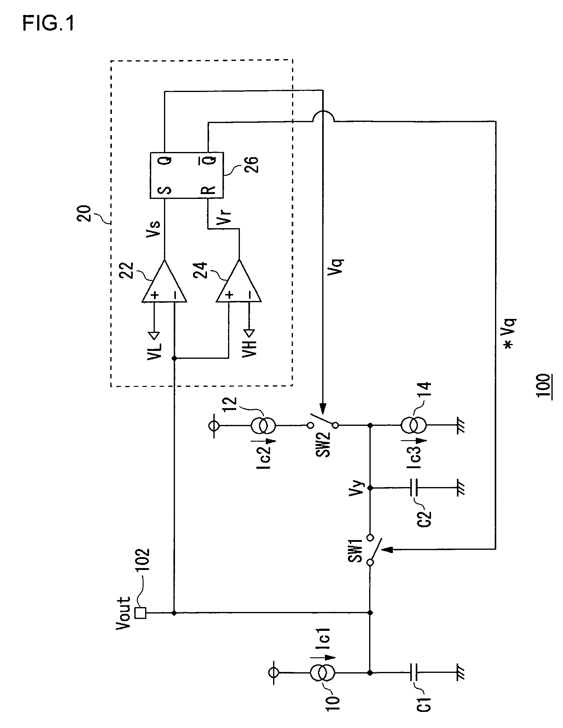
[0032]FIG. 1 is a circuit diagram showing a structure of a triangular wave generation circuit 100 according to an embodiment of the present invention. The triangular wave generation circuit 100 is comprised of a first capacitor C1, a second capacitor C2, a first constant-current source 10, a second constant-current source 12, a third constant-current source 14, a switch controller 20, a first switch SW1, and a second switch SW2.

[0033]The first terminal of the first capacitor C1 is grounded, and the potential is fixed. The first constant-current source 10 is connected to a second terminal of the first capacitor C1 and supplies a charging current to the second terminal of the first capacitor C1. Here...


PUM


Abstract

A first constant-current source supplies a charging current to a second terminal of a first capacitor in which a first terminal is grounded. A first terminal of a second capacitor is grounded, and a first switch is provided between the second terminal of the first capacitor and a second terminal of the second capacitor. A second constant-current source supplies current to the second capacitor, and a second switch is provided on a current path of the second constant-current source. A third constant-current source draws out current from the first capacitor and the second capacitor. A switch controller turns on the first switch and turns off the second switch when an output voltage appearing in the second terminal of the first capacitor reaches a predetermined upper-limit voltage. The switch controller turns off the first switch and turns on the second switch when the output voltage drops to a predetermined lower-limit voltage.

Description

BACKGROUND OF THE INVENTION[0001]1. Field of the Invention[0002]The present invention relates to a triangular wave generation circuit for generating triangular waves at a predetermined frequency.[0003]2. Description of the Related Art[0004]Pulse-width modulation techniques are widely used for power supply units such as switching regulators, or motor driver circuits for driving motors, and the like. For a pulse-width modulation, the error of a voltage to be controlled in relation to a target voltage is amplified by an error amplifier, and the error voltage resulting therefrom is compared by a comparator with a periodic voltage with a triangular waveform having a fixed frequency.[0005]To generate periodic voltages of triangular waveforms used in applications as mentioned above, analog triangular wave generation circuits as described in Reference (1) and Reference (2) in the following Related Art List are used widely. FIG. 3 is a circuit diagram illustrating a partially simplified stru...

Claims


Application Information

Patent Timeline
Patent Type & Authority Patents(United States)
IPC IPC(8): H03K4/06
CPCH03K4/06
Inventor UCHIMOTO, DAISUKEOYAMA, MANABU
Owner ROHM CO LTD
Why Eureka
Try Eureka