
System and method for cutting continuous web

a web and cutter technology, applied in the field of web cutters and cutter feeding systems, can solve the problems of insufficient cutting sheet size, permanent serpentine deformation, inconvenient and currently available cutters, etc., and achieve the effects of reducing air resistance, reducing inertial load, and small siz

Inactive Publication Date: 2008-07-29
ROLL SYST
View PDF7 Cites 18 Cited by
  • Summary
  • Abstract
  • Description
  • Claims
  • Application Information

AI Technical Summary

Benefits of technology

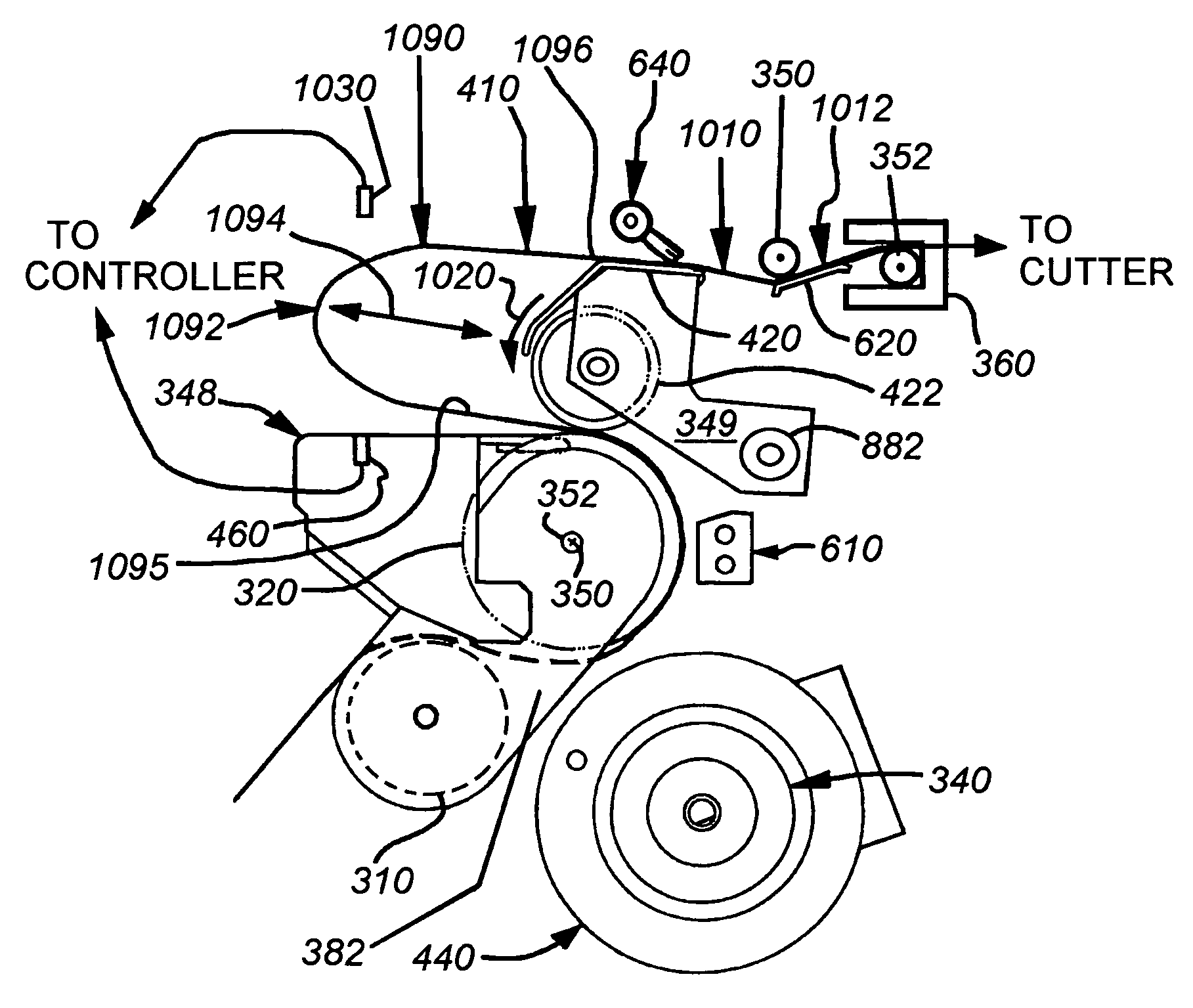
[0008]This invention overcomes the disadvantages of the prior art by providing a system and method for cutting continuous web that provides a simplified and direct feed path during loading, but that thereafter moves easily into a more-complex serpentine or S-wrap feed path for reliable infeed of the web from a source that is arranged as either a free loop or a moderately tensioned configuration. The serpentine feed path is provided at an infeed unit that infeeds web from an upstream source at a relatively continuous rate. Downstream, of the infeed unit, adjacent to a moving cutter element, is provided a cutter indexing drive. The cutter indexing drive moves intermittently to momentarily pause the web at the cutter knife until a cut occurs. The cutter indexing drive and infeed drive are synchronized by a controller so as to produce a small horizontally disposed buffer loop therebetween. The buffer loop is maintained within a predetermined range using a sensor, which is operatively connected with the controller, and that indicates the location of the end of the loop, modulating the drives to maintain the buffer loop's (returning) end within a predetermined location about the sensor's sensing field. The buffer loop makes possible a smooth transition from the continuous feed of the infeed drive to the intermittent feed of the indexing drive, while its small size generates minimal inertial load and reduced air resistance, and allows for better loop containment and control of the loop section. In addition, the inventive system includes an adjustment drive motor for moving a plurality of edge guide sets toward and away from each other in synchronization. In particular, the edge guides are adapted to move inwardly and outwardly with respect to a feed path centerline in an illustrative embodiment so that accurate centering of the web is maintained throughout the device's feed path.

Problems solved by technology

Conventional and currently available cutters are limited by a variety of disadvantages.
The tortuous web feed path, when maintained in a moderately tensioned state, is subjected to significant shock by the action of the cutter, which may lead to inaccuracy in the size of cut sheets—as the web is susceptible to sudden jerks during cuts.
In addition, the tortuous infeed path is difficult to thread during loading and, once threaded, may form a permanent serpentine deformation in the web when it is allowed to stand in the cutter for any significant waiting time.
This deformation can adversely affect feeding into downstream devices as the web presents an undesirable curl to the cutter, justifier, etc.
This is often accomplished by the operator through simple and inaccurate manual and visual techniques that may lead to misalignment between guides and off-center feeding.
This adjustment problem is exacerbated where a cutter is designed to feed either pin-feed or pinless web.

Method used


Image

  • System and method for cutting continuous web
  • System and method for cutting continuous web
  • System and method for cutting continuous web

Examples


Embodiment Construction

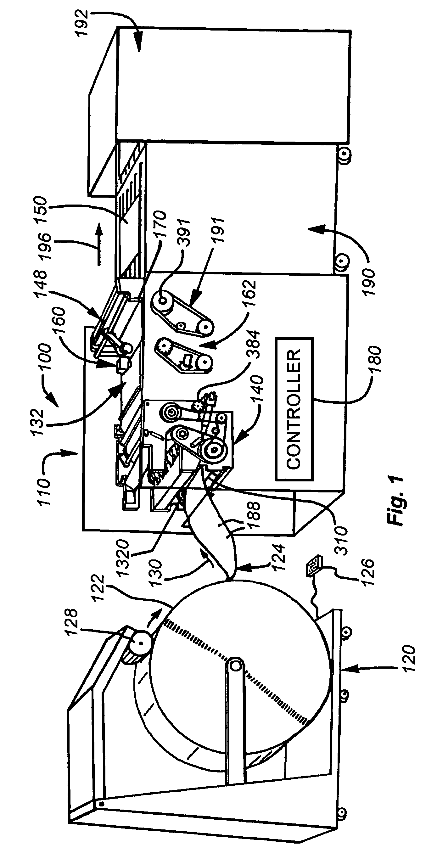
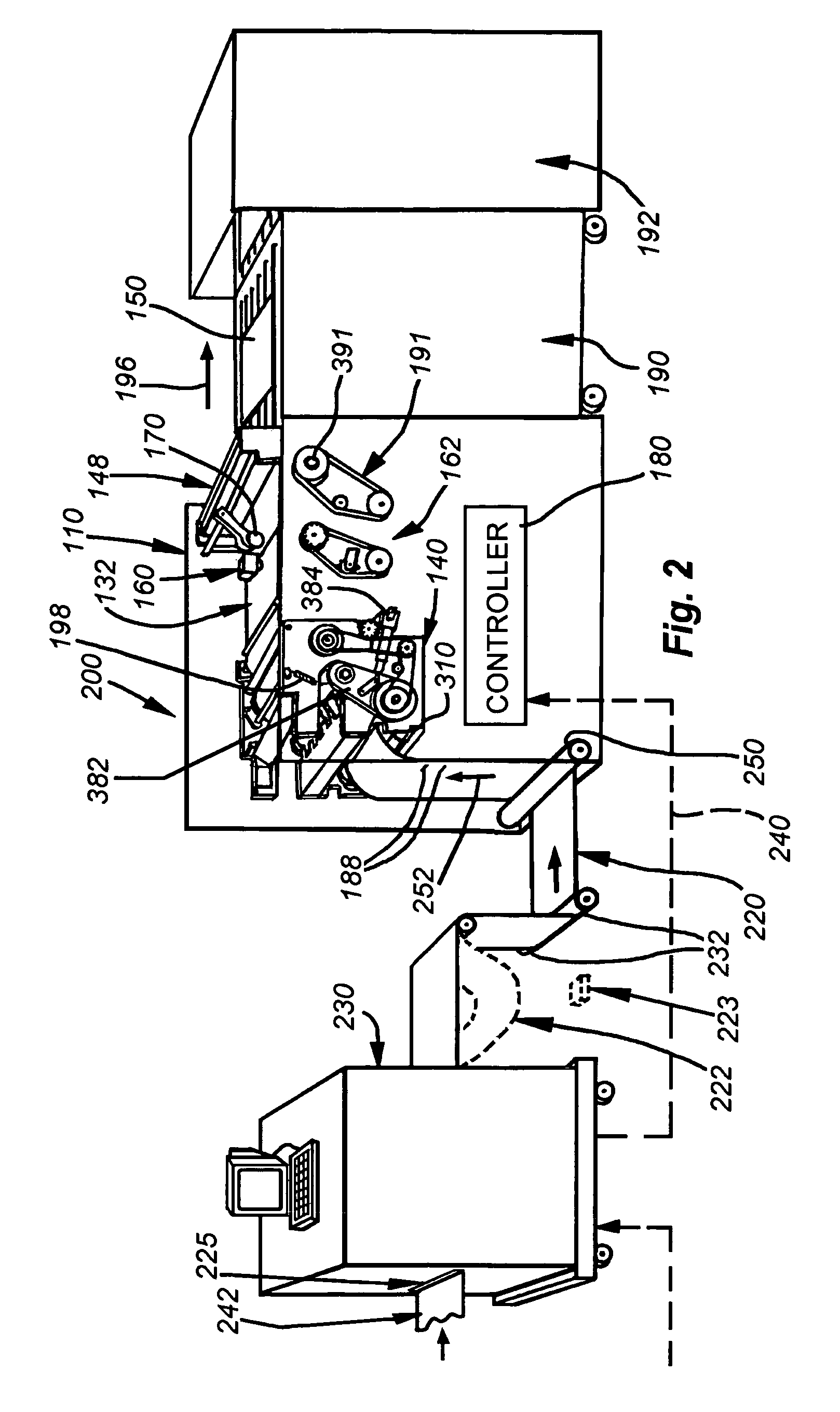
[0029]FIG. 1 shows an overall web handling system 100 that employs a cutter 110 according to an embodiment of this invention. The system 100 in this simplified embodiment includes a web source that is a driven roll stand 120 that provides web from a roll 122 on demand via a free loop 124 that is monitored by a sensor 126. The sensor 126 can be ultrasonic, optical or any other acceptable sensor-type that modulates the drive element 128 of the stand 120 so as to pay out web according to a desired rate. This source feed rate is typically based upon the draw demand from the cutter and downstream devices. The web is transferred in an upstream-to-downstream direction (arrow 130) through the free loop 124 and into the cutter 110 as needed. The cutter 110 includes an infeed section 140 that directs web from the free loop into the infeed unit 140 of the cutter (described in detail below) and upwardly through an upper indexing drive section 132, and finally through a cutter element 148. The c...


PUM

PropertyMeasurementUnit
outer diameteraaaaaaaaaa

Abstract

A system and method for cutting continuous web that provides a simplified and direct feed path during loading, and thereafter a more-complex serpentine feed path at an infeed unit for reliable infeed of the web, arranged as either a free loop or a moderately tensioned configuration. Downstream, an indexing drive intermittently pauses the web for the cutter knife to operate. The indexing drive and infeed unit's drive are synchronized by a controller to produce a small horizontally disposed buffer loop therebetween. The buffer loop is maintained within a predetermined range using a sensor, operatively with the controller, that measures the location of the end of the loop, modulating the drives to maintain the buffer loop's (returning) end within a predetermined location about the sensor's sensing field. The system includes an adjustment drive motor for moving a plurality of edge guide sets toward and away from each other in synchronization.

Description

BACKGROUND OF THE INVENTION[0001]1. Field of the Invention[0002]This invention relates to web cutters and cutter feeding systems.[0003]2. Background Information[0004]The use of continuous web for high speed printing operations, including print-on-demand and direct mail applications has become extremely popular. A continuous web, held on a driven roll, is driven through a series of stages in which printing and other embellishments are applied in the form of pages or sections of the web. The web can be driven through various printers and other web utilization devices while remaining in its continuous form. Web is generally driven through these utilization devices using a conventional tractor pin feed method in which perforated, pin feed strips along opposing side edges of the web are engaged by tractor pin feed units, or the web can be driven using a pinless feed method and drive, such as that described in U.S. Pat. No. 5,967,394 entitled METHOD AND APPARATUS FOR PINLESS FEEDING OF WE...

Claims


Application Information

Patent Timeline
Patent Type & Authority Patents(United States)
IPC IPC(8): B65H20/04
CPCB65H20/04B65H35/04B65H23/042Y10T83/4529Y10T83/6648
Inventor FISKE, JOHN M.MAZUR, JAMES R.HETENYI, TAMASZANCHI, EDWARD J.BOLZA, WILLIAM F.MERCURIO, GREGORY
Owner ROLL SYST
Learn More