Hollow structure formed by rotational molding and method of manufacturing same

a technology of rotating molding and hollow structure, which is applied in the direction of tank vehicles, transportation items, manufacturing tools, etc., can solve the problems of tank burst, adversely affecting the structural integrity of the tank, and tank movement, so as to limit the movement of liquid carried, simple and cost-effective manufacturing

Active Publication Date: 2008-07-29
MICHAEL WILLIAM J
View PDF18 Cites 12 Cited by
  • Summary
  • Abstract
  • Description
  • Claims
  • Application Information

AI Technical Summary

Benefits of technology

[0010]Accordingly, it is an advantage of the present invention that a hollow walled structure is provided.
[0011]It is another advantage of the present invention that a hollow walled structure is provided that can withstand forces imposed on it by a material carried within the structure.
[0012]Another advantage of the present invention is that a hollow, walled structure is provided with baffles so as to limit movement of a liquid carried within the structure.
[0013]Yet another advantage of the present invention is that a hollow walled structure is simply and cost-effectively manufactured utilizing a rotational molding process.
[0014]The above and other advantages of the present invention are carried out in one form by a hollow walled structure that includes a shell having a wall defining an interior compartment. A first support is disposed within the interior compartment and engages the wall at a first location and a second location. A second support engages the wall at a third location and extends through the interior compartment to intersect the first support. The shell, the first support, and the second support are formed concurrently from a thermoplastic material by a rotational molding process.
[0015]The above and other advantages of the present invention are carried out in another form by a method of rotationally molding a hollow walled structure that includes a shell having a wall that defines an interior compartment, a first support and a second support disposed within the interior compartment. The method calls for providing a first mold section shaped according to a first portion of the shell and having a first protrusion section and a second support protrusion for abutting the first protrusion section. The method further calls for providing a second mold section shaped according to a second portion of the shell and having a second protrusion section. The second mold section is assembled with the first mold section to form a closed mold having a molding surface, with the second protrusion section abutting the first protrusion section in the closed mold. Thermoplastic material is introduced into the closed mold, and the mold is heated and rotated about at least two axes to melt and distribute the thermoplastic material about the molding surface. The mold is cooled, and the structure is removed from the mold. The structure includes the first and second supports disposed in the interior compartment, the first support being formed in response to distribution of the thermoplastic material on the first and second protrusion sections, and the second support being formed in response to distribution of the thermoplastic material on the second support protrusion.

Problems solved by technology

Although rotationally molded products are recognized for their strength and durability, rotationally molded tanks utilized for liquid transport and storage suffer from a number of problems.
For example, the force exerted on the inner surface of the tank by the liquid can adversely affect the structural integrity of the tank.
That is, the tank may bulge outwardly in response to the force and may fail causing the tank to burst.
This problem is exacerbated when the tank is large.
Another problem that arises is that the liquid within the tank acquires momentum as it is transported by a vehicle.
The forces associated with this sloshing further stresses the structural integrity of the tank.
More critically, the forces associated with this sloshing can have a destabilizing effect on the vehicle.
Such destabilization may cause the driver to lose control of the vehicle, or may cause the vehicle, or a trailer carrying the tank, to overturn.
The numerous elements and post-manufacturing installation drive up the overall cost and complexity of the tank.
In addition, such baffles do not typically strengthen the tank in order to withstand the forces imposed on the tank walls by the liquid.

Method used


Image

  • Hollow structure formed by rotational molding and method of manufacturing same
  • Hollow structure formed by rotational molding and method of manufacturing same
  • Hollow structure formed by rotational molding and method of manufacturing same

Examples


Embodiment Construction

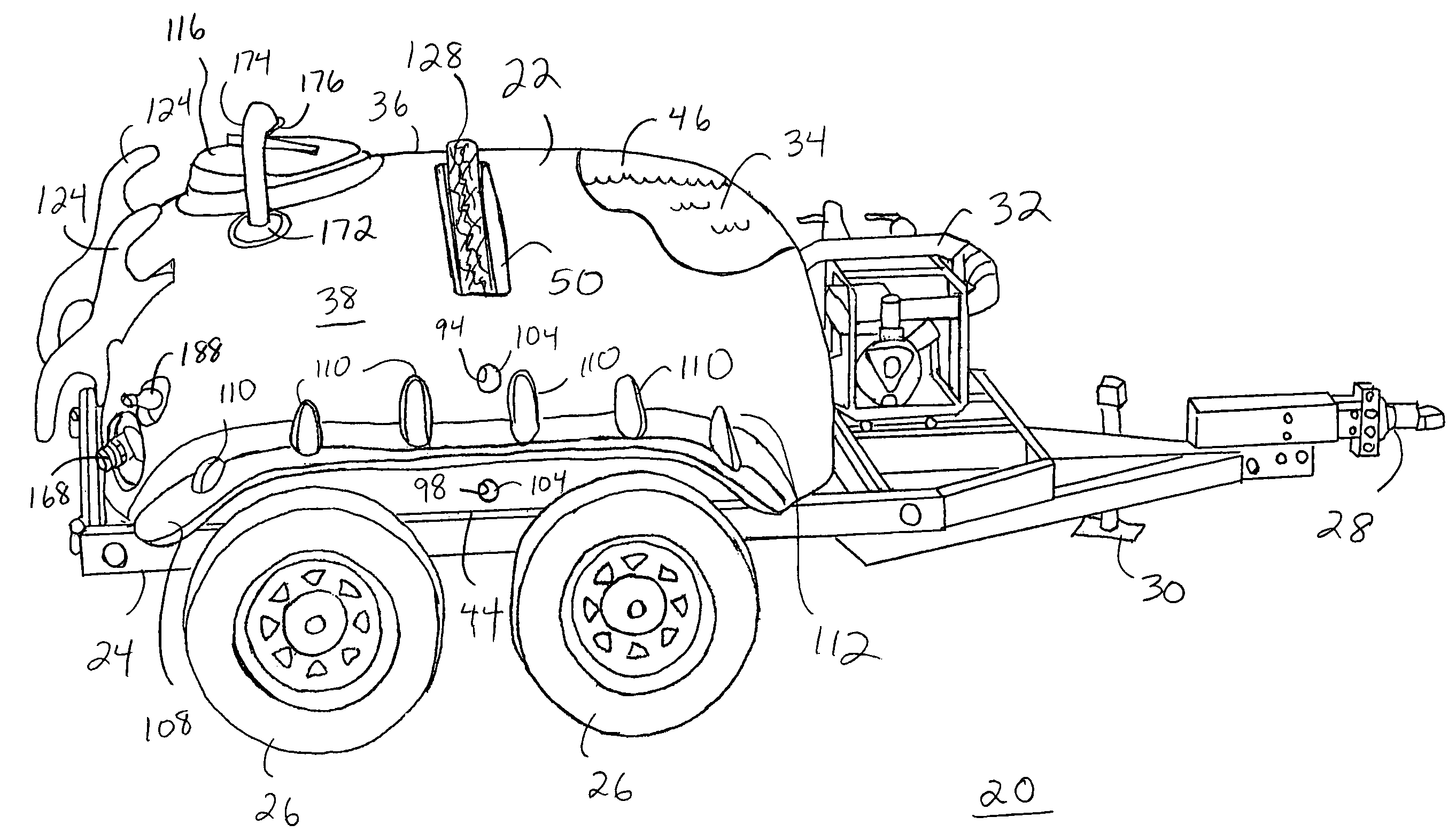
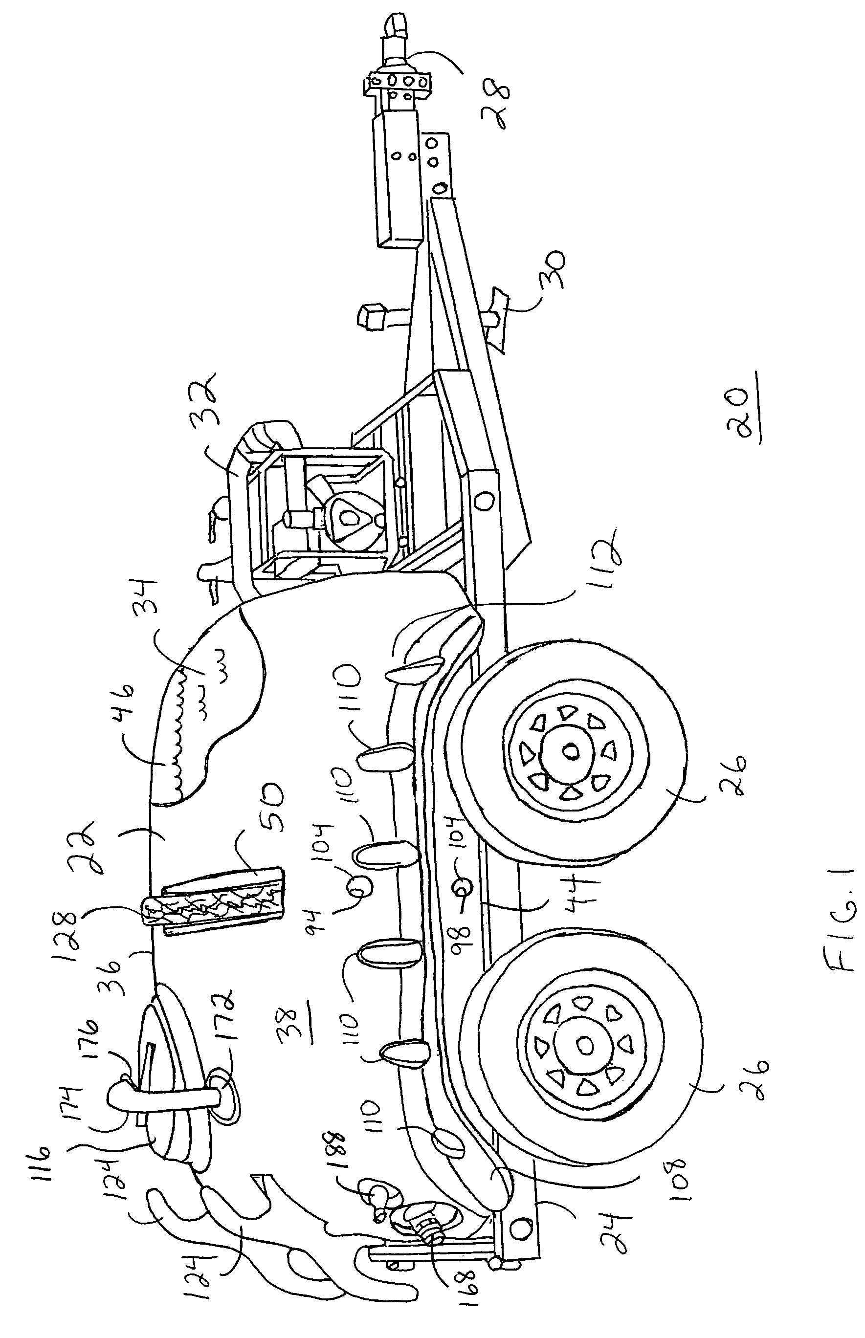
[0030]FIG. 1 shows a side view of a liquid transport apparatus 20 including a hollow walled tank 22 in accordance with a preferred embodiment of the present invention. Apparatus 20 generally includes tank 22, a frame 24 supporting tank 22, and wheels 26 rotationally coupled to frame 24. Apparatus 20 may further include a hitch mechanism 28 for attachment to a towing vehicle (not shown), a jack stand 30 for retaining apparatus 20 approximately horizontal when apparatus 20 is not being towed, and a pump system 32 for pressurized delivery of a liquid 34, such as water, stored in tank 22. Thus, frame 24, wheels 26, and hitch mechanism 28 form a wheeled trailer to which tank 22 is attached for transport.

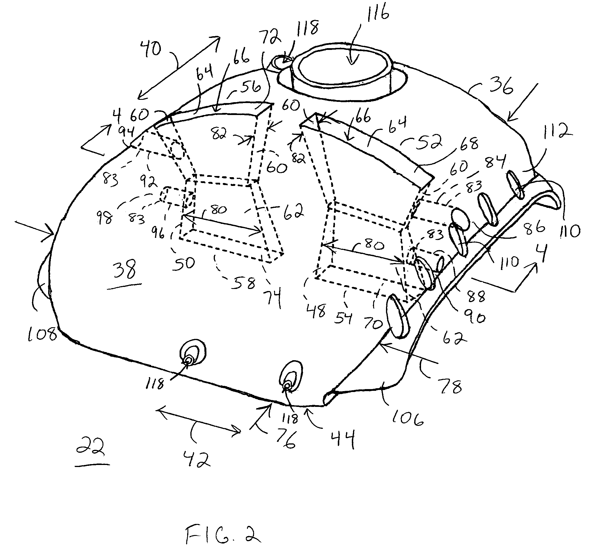
[0031]Tank 22 is a hollow walled structure formed from thermoplastic material, such as, polyethylene, polypropylene, acrylonitrile butadiene styrene (ABS), polyvinyl chloride (PVC), nylon, and the like. Tank 22 is manufactured utilizing a rotational molding process. A rotational molding t...


PUM

PropertyMeasurementUnit
weightaaaaaaaaaa
radiusaaaaaaaaaa
structureaaaaaaaaaa

Abstract

A hollow walled structure (22) includes a shell (36) having a wall defining an interior compartment (46). A first support, in the form of a baffle (48), is disposed within the interior compartment (46) and engages the shell (36) at two locations (52, 54). A second support, in the form of a post (83), engages the shell (36) and extends through the interior compartment (46) to intersect the baffle (48). The shell (36), baffle (48), and post (83) are formed concurrently from a thermoplastic material by a rotational molding process. The rotational molding process can entail operations of pre-heating interior portions of the mold, delivering heat to the interior portions of the mold, and / or filling the mold with excess thermoplastic material prior to preheating the mold. The rotationally molded structure (22) has sufficient strength to function as a tank for carrying a liquid (34) in a liquid transport apparatus (20).

Description

TECHNICAL FIELD OF THE INVENTION[0001]The present invention relates to hollow walled structures formed by rotational molding, and a method of making such hollow walled structures. More specifically, the present invention relates to a rotationally molded tank for a liquid transport apparatus.BACKGROUND OF THE INVENTION[0002]Plastic parts have the advantage of light weight, corrosion resistance and lower cost. One method for manufacturing some plastic parts is known as rotational molding, or rotomolding. Rotational molding is a process in which a hollow mold is loaded with a pre-measured plastic resin, and the mold is heated as it is slowly rotated bi-axially. The simultaneous heating and rotation causes the melting resin to generally coat the entire inner surface of the mold and fuse. The mold is then cooled and the plastic part is removed from the mold.[0003]Rotational molding results in seamless parts with generally uniform wall thickness and more material in corners to absorb shoc...

Claims


Application Information

Patent Timeline
Patent Type & Authority Patents(United States)
IPC IPC(8): B60P3/22
CPCB29C41/06B60P3/2205B29C41/386
Inventor MICHAEL, WILLIAM J.
Owner MICHAEL WILLIAM J
Why Eureka
Try Eureka