Hinge with stiffened leaf

a technology of hinge leaves and leaflets, applied in the direction of door/window fittings, multi-purpose tools, construction, etc., can solve the problems of not being usable with standard fasteners, prone to warpage and damage, lack of sufficient strength, etc., and achieve the effect of reducing actual distortion, masking remaining distortion, and high for

Active Publication Date: 2008-08-05
VON DUPRIN
View PDF9 Cites 12 Cited by
  • Summary
  • Abstract
  • Description
  • Claims
  • Application Information

AI Technical Summary

Benefits of technology

[0018]The present invention is generally directed to a longitudinally extending continuous hinge comprising specially formed leaves having a unique multi-level or -planar surface structure including a combination of raised and base portions. This offers the advantage of structurally stiffening the leaf allowing the use of thinner, stronger hinge leaf materials with improved strength and rigidity. Such thinner materials may preferably include steel which has superior fire resistance than aluminum which is commonly used for continuous hinges. The raised leaf portions further provide a recess or cavity on the underside of the leaves, and between the leaves and hinged objects when mounted thereto, to allow the creation of fuller depth, conically recessed screw holes than heretofore available. These cavities can also be filled with intumescent fire-resistant materials to improve the fire rating of the hinge. The present invention further provides interchangeability with existing industry standard continuous hinge door mounting clearances allowing hinge leaf materials to be easily switched without altering the door and frame. The present invention also allows the use of standard stronger fasteners without sacrificing attachment strength.
[0023]A hinge formed according to principles of the present invention further comprises each leaf having a plurality of fastener holes for mounting the hinge members to a hinged object. The holes preferably have a conical cross-sectional shape to allow the use of flat head conical mounting screws which are standard in the door hinge industry. Preferably, the fastener holes are located in the raised leaf portions described above; however, not all the holes need necessarily located in the raised portion. The holes in the raised portions preferably have a reinforcement on the underside of each leaf associated with each hole. The reinforcements, which may be annular or ring-like in configuration, preferably extend in a perpendicular direction outwards from the hole on the underside of the leaf. At least a portion of the reinforcement preferably defines a substantially flattened top for securely abutting a hinged object when the hinge member is mounted to the hinged object. Preferably, the hole reinforcements and the base portion or first planar level surface contact the hinged object when the hinge member is mounted thereto. The hole reinforcements add strength to the underside of the leaf and help prevent the fasteners from pulling through the leaf material when the leaf is mounted to a hinged object. The hole reinforcements also provides additional depth to the fastener hole allowing the use of standard fasteners to mount the leaf to a hinged object.

Problems solved by technology

These flat hinge leaves, however, may lack sufficient strength and are prone to warpage and damage when made of relatively thin material, such as sheet steel.
Due to the thinness of the material, they also may not be usable with standard fasteners used in the door hinge industry, such as No. 12 flat top, conical head self-tapping screws (either full or undercut head designs), and require special fasteners or modification of standard fastener offerings.
However, because of the variety of materials and processes used in their fabrication, together with their widespread availability from different sources, little attention has been given to interchangeability from one manufacturer's offerings to another, or between different choices of hinge leaf material such as aluminum or steel.
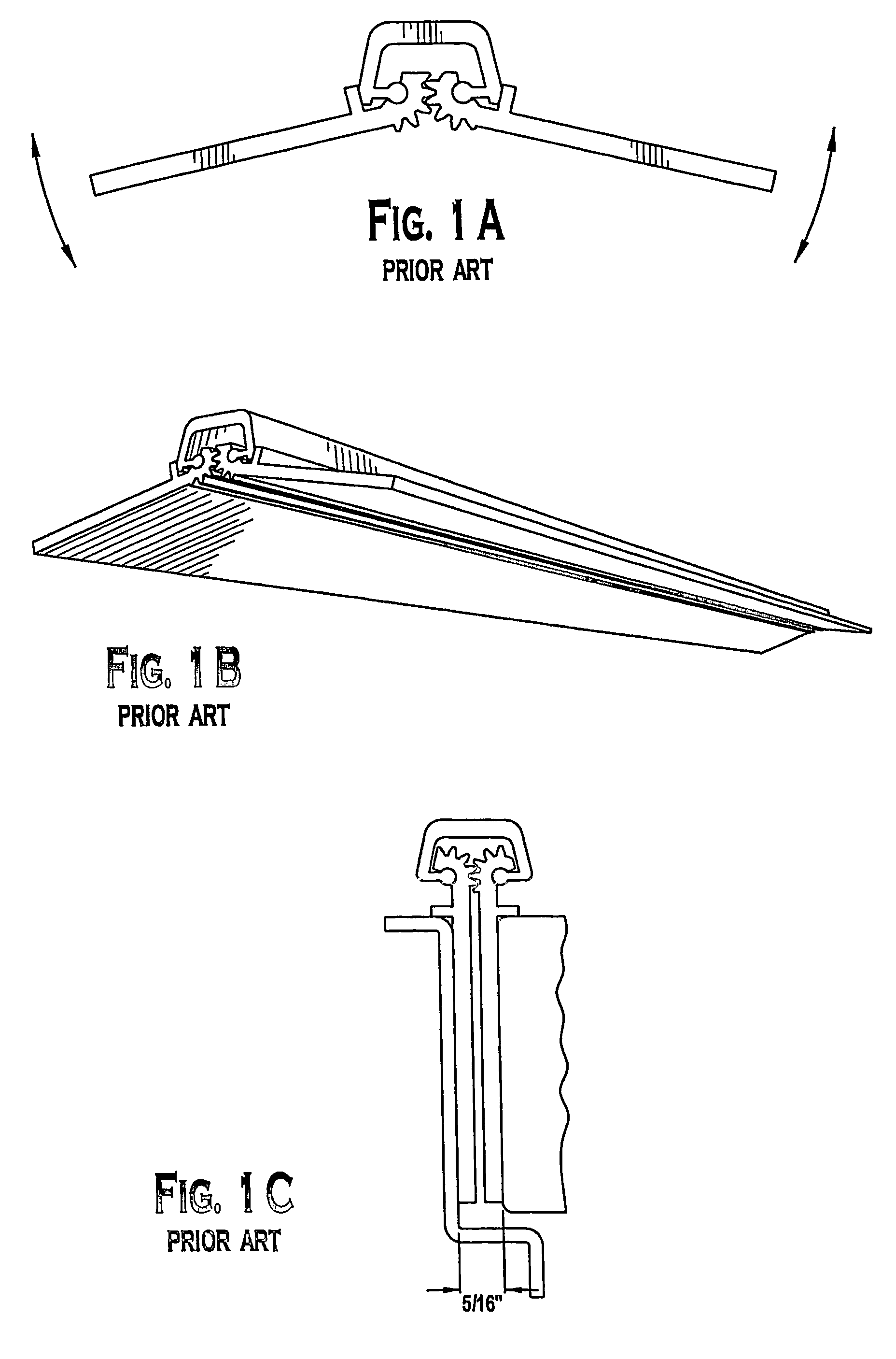
As is apparent, if a steel hinge having thinner leaves is desired to be substituted for the aluminum hinge, there is insufficient leaf thickness to fill the standard 5 / 16 inch gap, requiring costly and inconvenient door and / or frame modifications.
Even though the thinner leaves could be set wider apart by forming the knuckles to create a wider separation between them when the leaves are parallel, this would leave a large gap between them, which is undesirable because it would allow excessive air infiltration as well as permit warping and large distortions of the leaves under conditions of building fires in which steel hinges are principally intended.
Differences in resistance to the effects of fire and other operational hazards between continuous hinges that may be manufactured of different materials has made it difficult to exchange or replace hinges with others more suitable for a particular location in a building or for a different operating requirement.
The consequences of upfront errors by architects and designers that may occur in the specification of a particular hinge for a particular door assembly in new building construction or retrofit applications may be also be severe.
Frequently, the hinge specification must be changed during the construction sequence, because different hinge materials may be required for compliance with fire or other complex regulations, or must be changed during the useful life of the building because various building codes may be changed, or because the building may be used for subsequent, unanticipated purposes which require such changes.
As can be appreciated, continuous hinges which vary in thickness simply because of their materials of construction can create costly delays in the construction sequence and costly replacements of improperly sized frames and doors when errors in specification occur.
Current thin leaf hinges that are commercially available offer no such comparable interchangeability, resulting in the costly substitution of a new door and / or frame to meet the clearance requirements of alternate hinging systems.
Another difficulty arises in the fastening of continuous hinges to their doors and frames.
Undercut flat head screws, while useful for reducing the required depth of the countersink in hinges and similar hardware items, restrict the strength of the attachment, particularly if the head thickness is reduced too much.
If the head of the screw is too large in diameter in relation to its thickness and the body size of the screw, it could be so weak as to break in normal service, and it might be too thin to accept standard screwdriver tips commonly used with conventional screw driving tools that cooperate with the recess formed in the screw head.
If the screw heads are made the slightest bit thicker than the gauge of the hinge leaves, the screw head will “bottom” against the door or frame material before the leaf is forced and held tight against its supporting surface, resulting in a loose and weak hinge installation.
With steel hinges made of relatively thin-gauge fabricated sheet metal, however, these standard fastener offerings are often unsuitable having screw heads that exceed the thickness of the hinge leaf material by an unacceptable tolerance.
Thus screw heads must be severely undercut for use with the thin-gauge steel hinges, thereby weakening them.
However, this sacrifices shear strength and holding power, because unlike mortise or butt hinges which rely on the door and frame cutouts for door support, doors hung with continuous hinges must rely primarily on the strength of the screws alone to support the weight of the door.
The handling and shipping of continuous hinges presents yet another problem.
Hinges fabricated of steel sheet metal in long lengths are easily bowed, dented, and bent during their shipment, handling at the jobsite, or during installation.
Yet another disadvantage of sheet metal hinges is difficulty in maintaining proper appearance after installation, because the screw tension at widely separated screw locations along the length of each hinge member distorts the material, producing highly visible waviness and unsightly reflections in the finished installation.
This is particularly unacceptable for commercial installations.
Otherwise, only those types of screws which have a head that projects above the surface of the hinge leaf could be employed, making the installation both unsightly and producing a wide gap between the hinges leaves in the closed position.
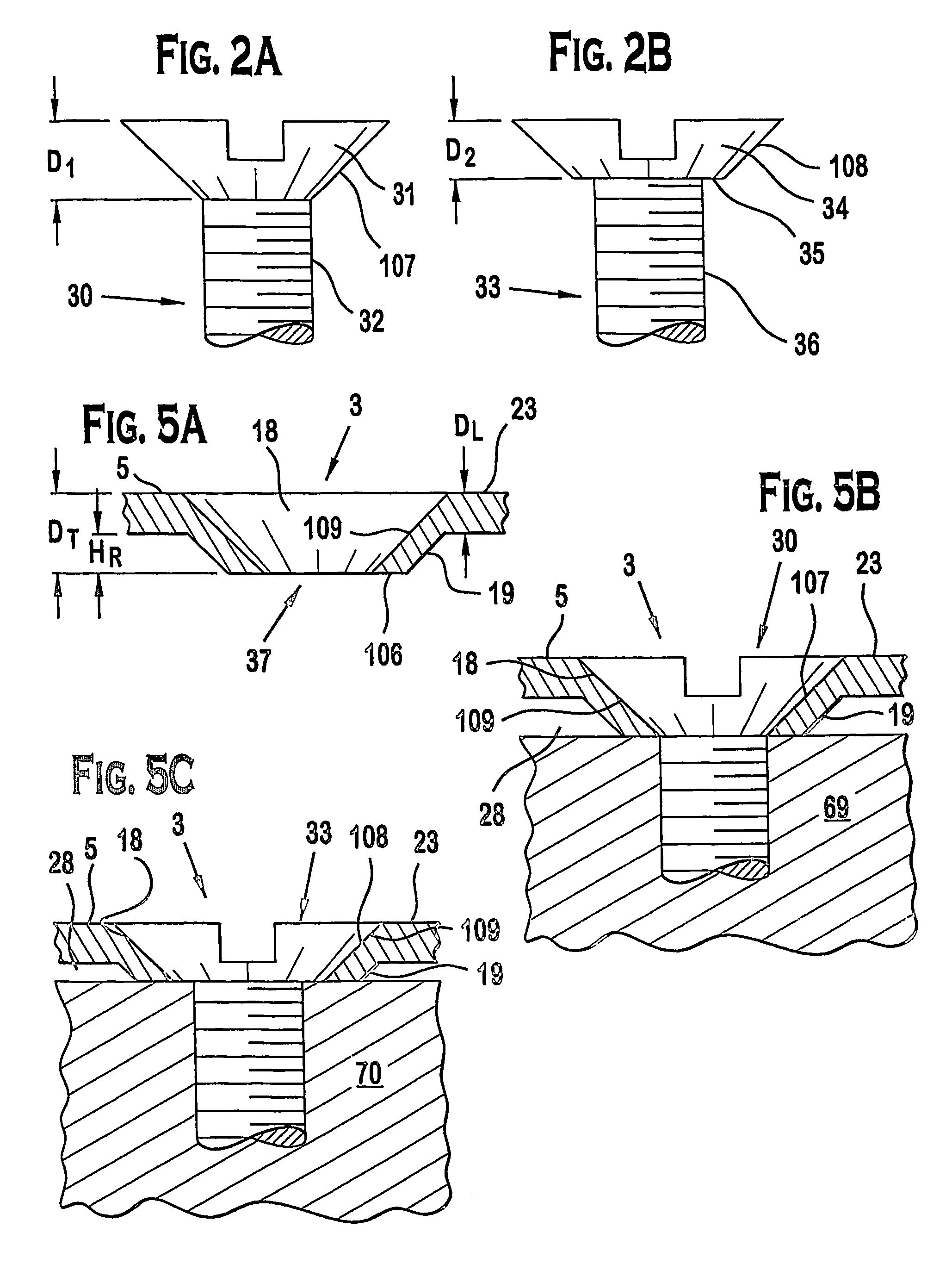
In other manufacturing techniques, a slightly beveled rim can be stamped around the edge of each hole, but the depth and conformity to the screw head design is limited by the extremely high forces required in “coining” these edges and the durability of the forming punches to withstand the pressures needed to produce metal flow within the material thickness of the leaves.
Moreover, these limits of press-formed conical shapes require that the initial hole be initially stamped to a much larger diameter than the body or shank of the screw would normally otherwise require, because the limited ability of the metal to flow into a conical shape limits the bevel to the outer edges of the hole.
Flat head countersunk screws contact such screw holes around their outer edges only, creating hinge leaf screw pull-through problems when the leaf is being fastened to a hinged object and screw breakage because of the leverage effect between the outer edges of severely undercut thin-headed screws and their sharp edged (stress concentration notch) transition to the screw body.

Method used


Image

  • Hinge with stiffened leaf
  • Hinge with stiffened leaf
  • Hinge with stiffened leaf

Examples


Embodiment Construction

[0057]It should be recognized that while the present invention is described and illustrated with reference to particular preferred embodiments, the scope of the invention is not intended to be limited to such embodiments. Furthermore, the description of the invention the follows, and any references to orientation, configuration, direction, size, or materials, is intended primarily for convenience and does not limit the scope of the present invention.

[0058]The longitudinal direction is herein defined as extending in a direction generally parallel to the longitudinal axis LA along the length of the hinge 1, as shown in FIG. 8. The transverse direction is defined herein as extending in a direction generally perpendicular to the longitudinal axis LA, along the transverse axis TA as shown in FIG. 4C.

[0059]Referring now to FIGS. 4A-C, there is shown an improved continuous hinge 1 according to a preferred embodiment of the invention. These Figures show the hinge 1 in various positions, inc...


PUM


Abstract

A hinge including a stiffened leaf. The hinge may generally comprise a first longitudinally-extending leaf having a base portion and a mounting portion offset and preferably parallel to the base portion that defines a cavity. The mounting portion may contain at least one hole for attaching the leaf to a hinged object with a fastener. In one embodiment, the hole further includes an annular reinforcement disposed in the cavity proximate to the hole. The hole may be conical in shape and may extend into the reinforcement to receive and support a conically-shaped fastener head. The hinge is suitable for thin leaf construction and continuous full-length hinge applications.

Description

CROSS-REFERENCE TO RELATED APPLICATIONS[0001]The present application is a U.S. National Phase Application of International Application PCT / 2004 / 020870 (filed Jun. 30, 2004) which claims the benefit of U.S. Provisional Application No. 60 / 483,853 (filed Jun. 30, 2003), all of which are herein incorporated by reference in their entirety.BACKGROUND OF THE INVENTION[0002]The present invention relates to continuous hinges for use with architectural doors and frames. More particularly the invention relates to forming hinge leaves for continuous hinges to facilitate and improve their secure attachment with threaded fasteners by stiffening the metal leaves of such hinges through embossing or other means to produce a unique surface structure. The invention further relates to a hinge leaf fastener hole configuration and structure, and methods for forming the same, to optimize the choice of fasteners and improve the strength of such holes. These features will facilitate interchangeability of th...

Claims


Application Information

Patent Timeline
Patent Type & Authority Patents(United States)
IPC IPC(8): E05D7/00E05DE05D3/06E05D9/00
CPCE05D3/022E05D5/04E05D5/06E05D7/009E05D9/00E05D3/122Y10T16/541E05Y2800/416E05Y2800/674E05Y2800/26Y10T16/558Y10T16/554Y10T16/538633E05Y2201/222E05Y2900/132
Inventor BAER, AUSTIN R.
Owner VON DUPRIN
Why Eureka
Try Eureka