Exhaust gas throttle valve for engines

a technology of exhaust gas and throttle valve, which is applied in the direction of machines/engines, exhaust treatment electric control, separation processes, etc., can solve the problems of large noise, large noise, and deposited part part dpf burns, and achieves simple cutting and machining. , the effect of reducing the noise generated

Inactive Publication Date: 2008-08-05
ISUZU MOTORS LTD
View PDF15 Cites 11 Cited by
  • Summary
  • Abstract
  • Description
  • Claims
  • Application Information

AI Technical Summary

Benefits of technology

[0016]In order to decrease the amount of the exhaust gases that flow between the valve body and the tubular wall of the exhaust gas passage, and consequently, to decrease the noise as small as possible, it can be contrived to perforate communication holes in the valve body of the exhaust gas throttle valve, so that the exhaust gases are discharged through the communication holes when the diesel engine is in operation while closing the exhaust gas throttle valve. For this purpose, the circumferential portion of the valve body must be brought close to the tubular wall of the exhaust gas passage when the valve is closed to minimize the gap therebetween as much as possible.
[0026]The above constitution makes the exhaust gas throttle valve of the present invention to exhibit the following function and effect.
[0028]The distance between a point on circumferential portion of the valve body and the opposing tubular wall of the exhaust gas passage becomes smaller as the point on circumferential portion approaches the center axis of rotation. The position of the recessed portion is the one where the distance becomes the smallest between the circumferential portion and the edge portion throughout the whole circumference of the valve body, and is, hence, the position where the valve body and the edge portions become most likely to come in contact with each other in case the exhaust gas throttle valve is thermally expanded due to the exhaust gases of a high temperature. In the present invention, recessed portions are formed in these positions to increase the gap and, hence, to avoid the probability of contact caused by the thermal expansion. This makes it possible to carry out the designing to minimize the gap as a whole between the circumferential portion of the valve body and the tubular wall of the exhaust gas passage. This decreases the amount of the exhaust gases flowing around the circumference of the valve body when the exhaust gas throttle valve is closed and decreases the noise that generates. Besides, the above effect is obtained by a simple machining of cutting the surface of the valve body without boosting the cost of production substantially.
[0029]It is desirable as described in claim 2 that the recessed portions are so shaped that the depth is a maximum at points where the circumferential portion of the valve body faces the edge portions. When the recessed portions are formed in this shape, the above-mentioned effect is achieved most effectively, and the gap as a whole can be minimized between the circumferential portion of the valve body and the tubular wall of the exhaust gas passage.
[0031]A large quantity of heat is exerted on the exhaust gas throttle valve at the time of forced regeneration when the exhaust gas throttle valve is used in combination with the device for purifying the exhaust gases, that has a catalyst and a diesel particulate filter for trapping the particulate matter in the exhaust gases. As described in claim 4, therefore, it is desired to use the exhaust gas throttle valve of the present invention as the exhaust gas throttle valve for a diesel engine equipped with the device for purifying the exhaust gases. In this case as described in claim 5, the invention exhibits the effect more efficiently when the exhaust gas throttle valve is disposed on the downstream of the device for purifying the exhaust gases.
[0032]In addition to the exhaust gas throttle valve used in combination with the device for purifying the exhaust gas, it is noted that the exhaust gas throttle valve according to the present invention can be adopted as an exhaust brake valve disposed in the exhaust system of the engine, that is used in heavy duty vehicles and that is so operated as to decrease the opening degree during the deceleration operation of the vehicle. The exhaust brake valve, too, is thermally expanding due to the exhaust gases of high temperatures. As described in claim 6, therefore, the present invention can be applied to the exhaust brake value to avoid the stick caused by the thermal expansion.

Problems solved by technology

Besides, the particulate matter deposited on the DPF burns.
Accordingly, the temperature on the downstream of the continuously regenerating DPF is further elevated and sometimes exceeds 600° C. Therefore, a very large quantity of heat affects on the exhaust gas throttle valve disposed on the downstream of the continuously regenerating DPF, and the thermal expansion of the constituent parts becomes to a serious degree.
The high pressure exhaust gas vigorously flows out through the gap between the circumferential portion of the valve body of the exhaust gas throttle valve and the tubular wall of the exhaust gas passage, so that a large noise is made from the circumference of the exhaust gas throttle valve accompanied by a pressure drop of the exhaust gas.
When the exhaust gas throttle valve is disposed at the downstream of the continuously regenerating DPF, however, a decrease in the noise by the continuously regenerating DPF cannot be expected.
If the valve body is designed to be brought close to the tubular wall of the exhaust gas passage to decrease the noise, they become in contact together (so-called biting) when they are thermally expanded, and the valve body may be stuck.

Method used


Image

  • Exhaust gas throttle valve for engines
  • Exhaust gas throttle valve for engines
  • Exhaust gas throttle valve for engines

Examples


Embodiment Construction

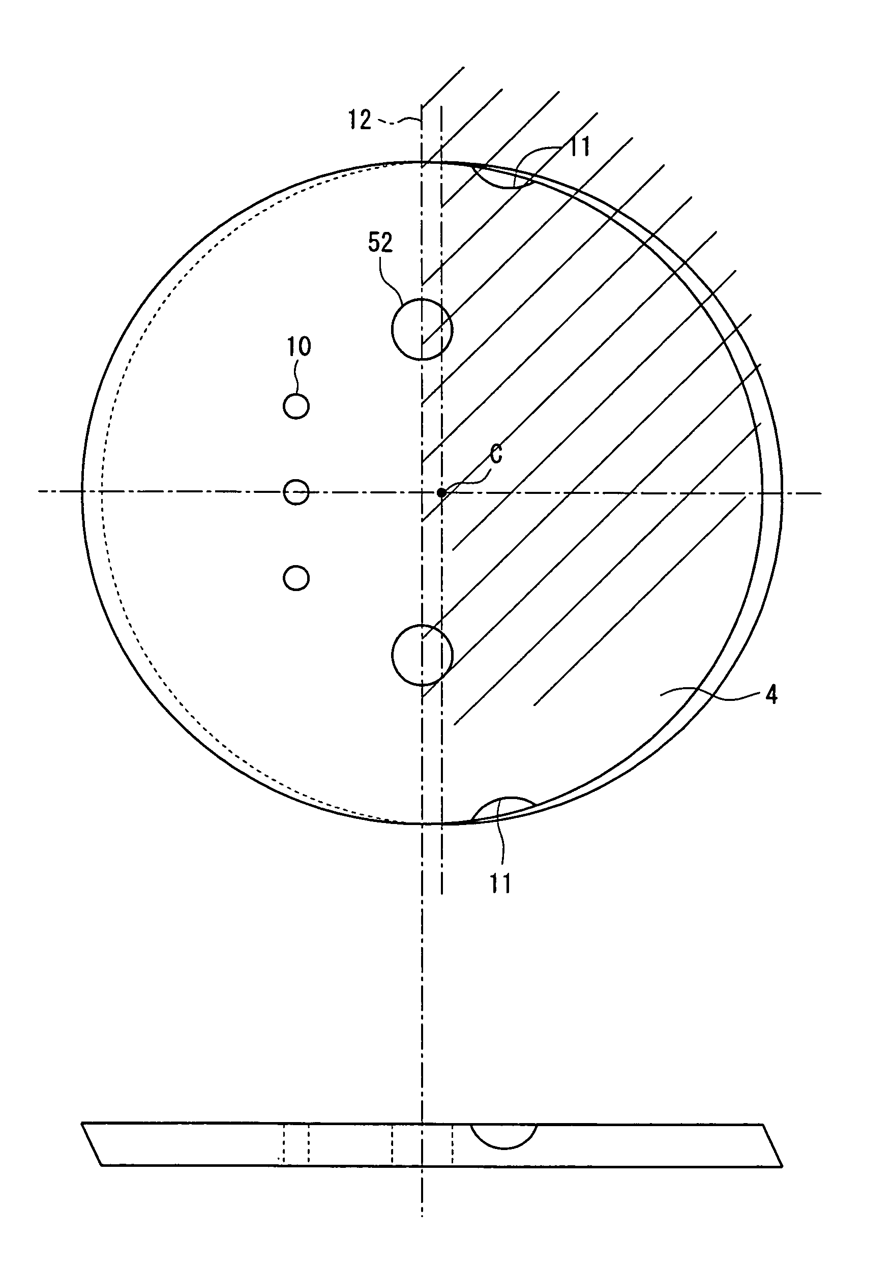
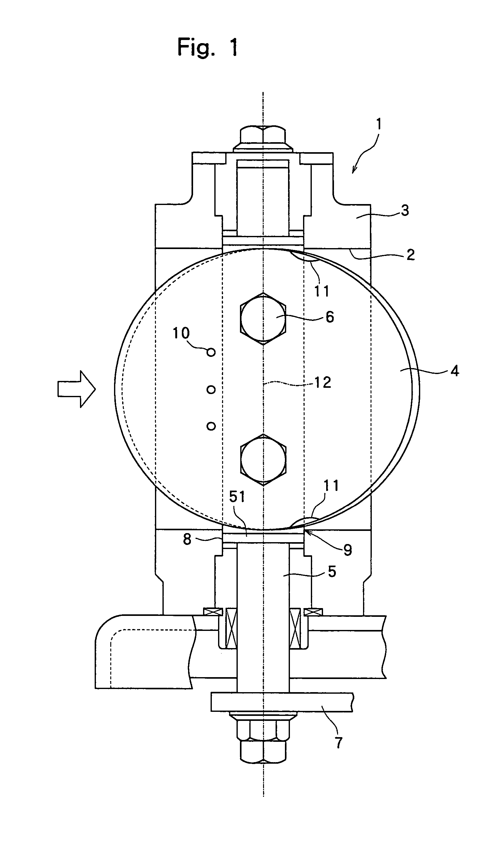
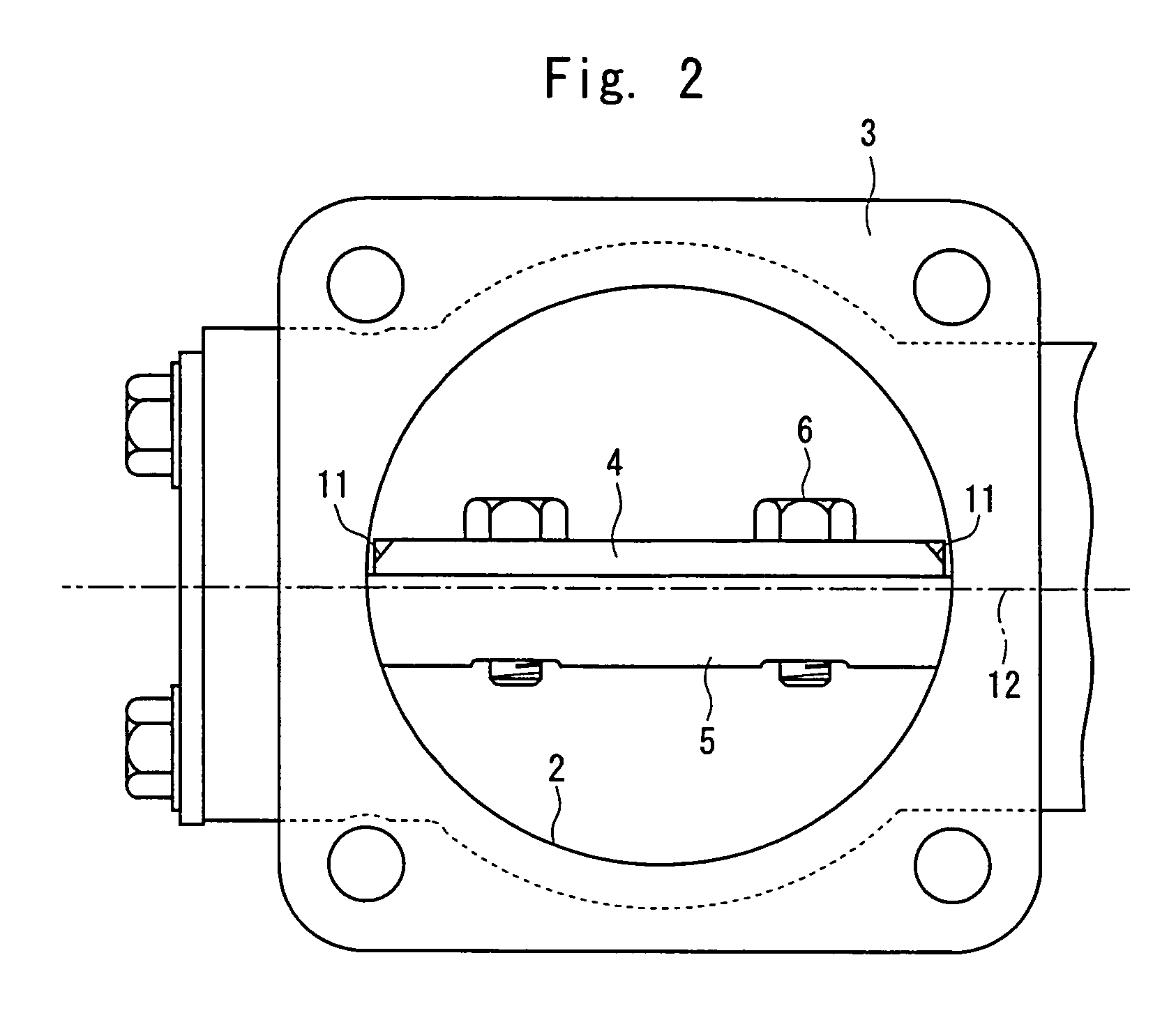
[0041]An exhaust gas throttle valve of the present invention will now be described with reference to the drawings. Here, the invention is concerned with the exhaust gas throttle valve itself, and, the constitution and operation of a device for purifying the exhaust gases to which the exhaust gas throttle valve is applied are the same as those of FIG. 8, hence, they are not described here in detail. In the drawings of the exhaust gas throttle valve of the invention, further, the parts and devices corresponding to those of the prior art (FIG. 7) are denoted by the same reference numerals.

[0042]The exhaust gas throttle valve illustrated in FIGS. 1 and 2 is a butterfly valve arranged in a valve casing 3 in which an exhaust gas passage 2 is formed, like the one shown in FIG. 7. A valve shaft 5 to which a valve body 4 is attached has a shape which is the same as that of the valve shaft of FIG. 7, and has both end portions thereof fitted into insertion holes 8 formed in the valve casing 3....


PUM

PropertyMeasurementUnit
temperatureaaaaaaaaaa
circular shapeaaaaaaaaaa

Abstract

An exhaust gas throttle valve disposed in the exhaust system of an engine, wherein the center axis of rotation of a valve shaft 5 is set at a position deviated from the center axis of the exhaust gas passage, and two recessed portions 11 are symmetrically formed in the circumferential portion of a valve body 4 by cutting the surface thereof. The positions where the recessed portions 11 are formed are on the side of the center axis of the exhaust gas passage beyond the center axis 12 of rotation, and at where the peripheral portion of the valve body 4 faces the edge portions 9 where insertion holes 8 for the valve shaft 5 are opened in the exhaust gas passage. At these positions, the distance is a minimum between the peripheral portion of the valve body 4 and the edge portions 9. The recessed portions 11 work to increase the gap relative to the edge portions 9 at that positions. It is therefore made possible to approximate the peripheral portion of the valve body 4 to the tubular wall of the exhaust gas passage 2 when the exhaust gas throttle valve is closed preventing the valve body 4 and the edge portions 9 from coming in contact together despite of the thermal expansion.

Description

BACKGROUND OF THE INVENTION[0001]1. Field of the Invention[0002]The present invention relates to a structure of an exhaust gas throttle valve provided in the exhaust system of an engine, such as a throttle valve disposed on the downstream of a device for purifying the exhaust gases of a diesel engine or an exhaust brake valve for assisting the braking force during the deceleration operation of a vehicle.[0003]2. Description of the Related Art[0004]As an important way to protect the environment, regulations have now been legislated for reducing pollution components contained in the exhaust gases emitted from the engines for vehicles, and a variety of technologies have been vigorously developed to reduce pollution components. In particular, the regulations against the exhaust gases of diesel engines are becoming stringent in recent years, and it is expected that more strict regulations will be legislated in the future. Diesel engines generally feature a higher thermal efficiency than ...

Claims


Application Information

Patent Timeline
Patent Type & Authority Patents(United States)
IPC IPC(8): F01N7/00F01N3/00F02D9/08B01D46/42F01N3/023F01N3/24F01N9/00F01N13/08F02D9/04F02D9/06F02D9/10
CPCF01N3/0231F01N3/0235F01N3/106F01N9/002F01N13/0097F02D9/04F01N2250/02F01N2260/10F01N2390/04F01N2430/085F02D9/06Y02T10/47F01N2390/00Y02T10/40
Inventor TAKAHASHI, HIDEKI
Owner ISUZU MOTORS LTD
Why Eureka
Try Eureka