Illumination device with arms that open after passing through a hole

a technology of a slit and a hole, which is applied in the direction of household objects, light fastenings, garments, etc., can solve the problems of not being able to fit lamps in standard automotive lamp sockets, unable to meet the needs of lamps, and unable to achieve the effect of increasing the lighting

Inactive Publication Date: 2008-08-05
TASSON ANTONIO +1
View PDF22 Cites 38 Cited by
  • Summary
  • Abstract
  • Description
  • Claims
  • Application Information

AI Technical Summary

Benefits of technology

[0012]Another object of the invention is to provide an illumination device that can use multiple light emitting devices such as LEDs to provide a greater amount of lighting than would be available with a single light emitting device.
[0015]Another object of the invention is to provide a distributed layout for the light sources that will allow one or more individual lighting elements to operate with sufficient thermal heat dissipation to allow proper operation of the device.

Problems solved by technology

The function of multiple LEDs in close proximity to each other within a confined area could be limited or prevented by an inability to adequately dissipate the heat produced by the LEDs.
These lamps are not designed to fit through a standard automotive light module mounting hole and do not fit in standard automotive lamp sockets.

Method used


Image

  • Illumination device with arms that open after passing through a hole
  • Illumination device with arms that open after passing through a hole
  • Illumination device with arms that open after passing through a hole

Examples


Embodiment Construction

[0027]Detailed descriptions of the preferred embodiment are provided herein. It is to be understood, however, that the present invention may be embodied in various forms. Therefore, specific details disclosed herein are not to be interpreted as limiting, but rather as a basis for the claims and as a representative basis for teaching one skilled in the art to employ the present invention in virtually any appropriately detailed system, structure or manner.

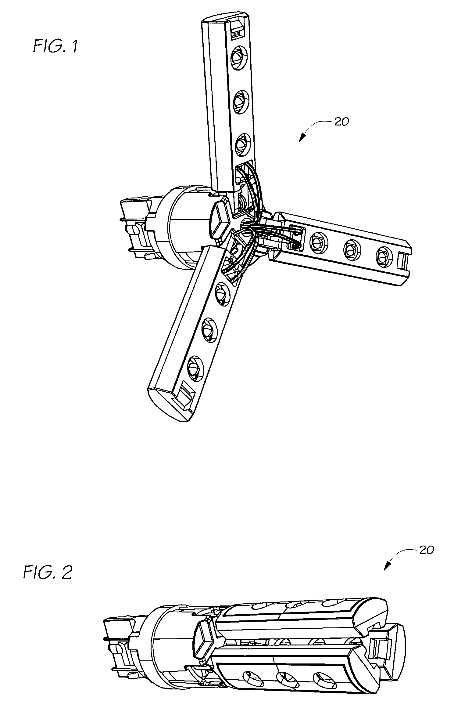
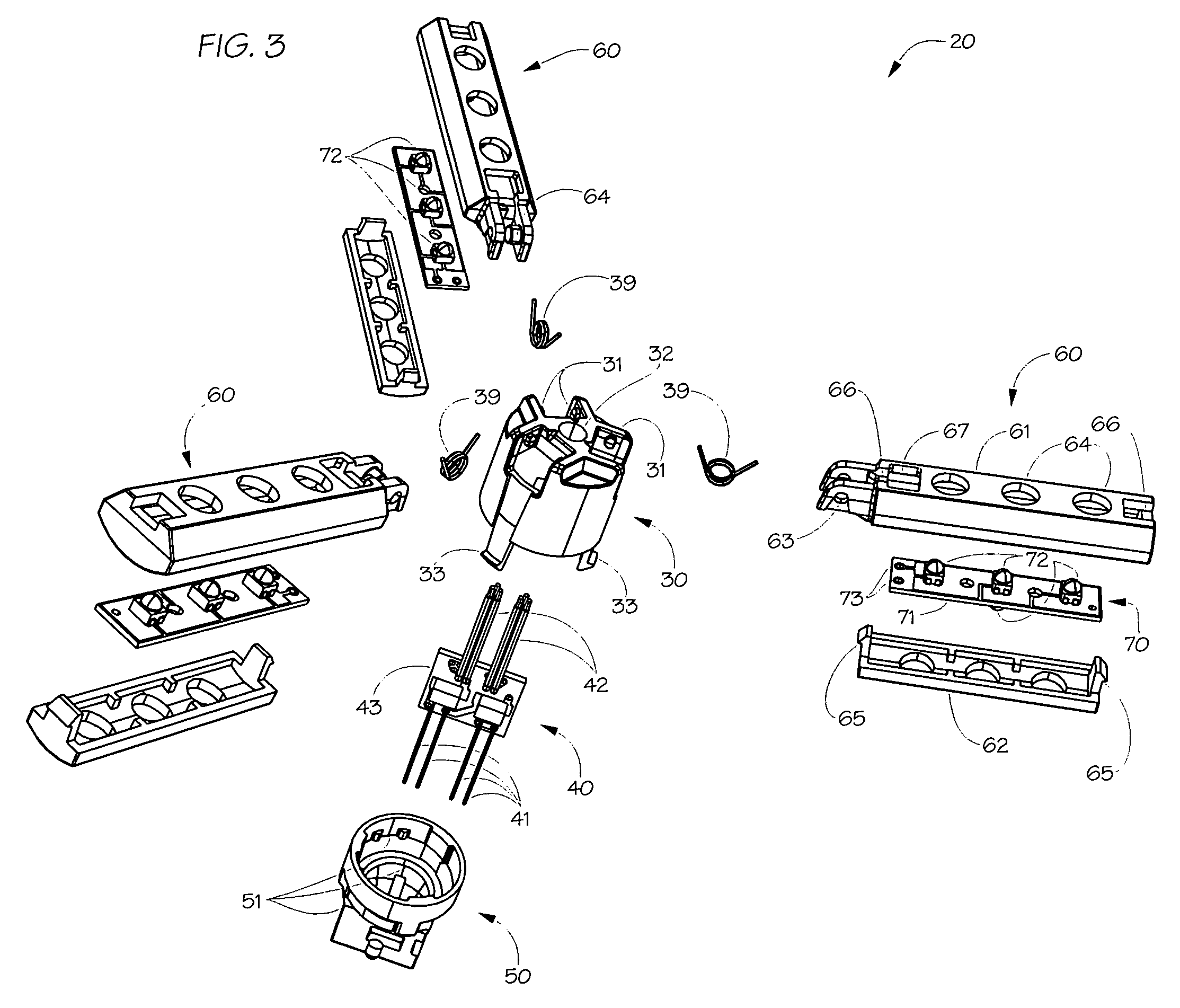
[0028]The above described drawing figures illustrate the invention, an illumination device with arms that open after passing through a hole 20 for use in a housing designed for an incandescent light bulb such as the taillight module 81 of an automobile 80 or similar vehicle. In the preferred embodiment, the invention 20 can function as a brake signal, turn signal, taillight, headlight or other application.

[0029]As shown in FIGS. 1-3, an embodiment of the present invention includes a body 30 that provides a structure to support the ar...


PUM


Abstract

An illumination device including at least one arm supporting one or more light emitting devices, such arm pivoting from a closed configuration for passing through a hole to an open configuration for function. In a preferred embodiment, the illumination device includes three or five arms, light emitting diodes (LEDs) as the light emitting devices and, springs for automatically pivoting the arms to the open configuration.

Description

CROSS REFERENCE TO RELATED APPLICATIONS[0001]This application is based on provisional application Ser. No. 60 / 517,946, filed on Nov. 6, 2003.STATEMENT REGARDING FEDERALLY SPONSORED RESEARCH OR DEVELOPMENT[0002]Not ApplicableDESCRIPTION OF ATTACHED APPENDIX[0003]Not ApplicableBACKGROUND OF THE INVENTION[0004]This invention relates generally to the field of illumination devices and more specifically to illumination devices where a light bulb or other device is typically installed through an opening into a housing.[0005]The preferred embodiment of the present invention is particularly useful for replacing incandescent lamps used in automobiles, boats, aircraft and other vehicles, where the invention would be applied as a replacement for incandescent bulbs and use light emitting diodes (LEDs) as the source of illumination. Current LED devices produce very directional light emission. The placement and location of these LEDs in a light module should be spread out to maximize the projected...

Claims


Application Information

Patent Timeline
Patent Type & Authority Patents(United States)
IPC IPC(8): F21V21/26F21S8/10B60Q1/26F21K99/00F21V21/14
CPCB60Q1/2607F21K9/58F21Y2101/02F21V21/30F21K9/65F21Y2115/10F21S43/14F21S43/15
Inventor TASSON, ANTONIOLIAO, RONNY
Owner TASSON ANTONIO
Why Eureka
Try Eureka