Liquid crystal device, compositions and method of manufacture

Active Publication Date: 2008-08-05
HEWLETT PACKARD DEV CO LP
View PDF13 Cites 2 Cited by
  • Summary
  • Abstract
  • Description
  • Claims
  • Application Information

AI Technical Summary

Benefits of technology

[0029]and a structure that reduces anchoring energy and/or viscosity of the liquid crystal at said surface alignment structure, said structure comprising non-polymerisabl

Problems solved by technology

One problem with the use of oligomers or short chain polymers in prior art devices is that the polymerisation process results in a range of molecular weights, and the anchoring properties vary with different molecular weight ranges.
This can lead to difficulties in reproducing the desired properties in a manu

Method used


Image

  • Liquid crystal device, compositions and method of manufacture
  • Liquid crystal device, compositions and method of manufacture
  • Liquid crystal device, compositions and method of manufacture

Examples


Embodiment Construction

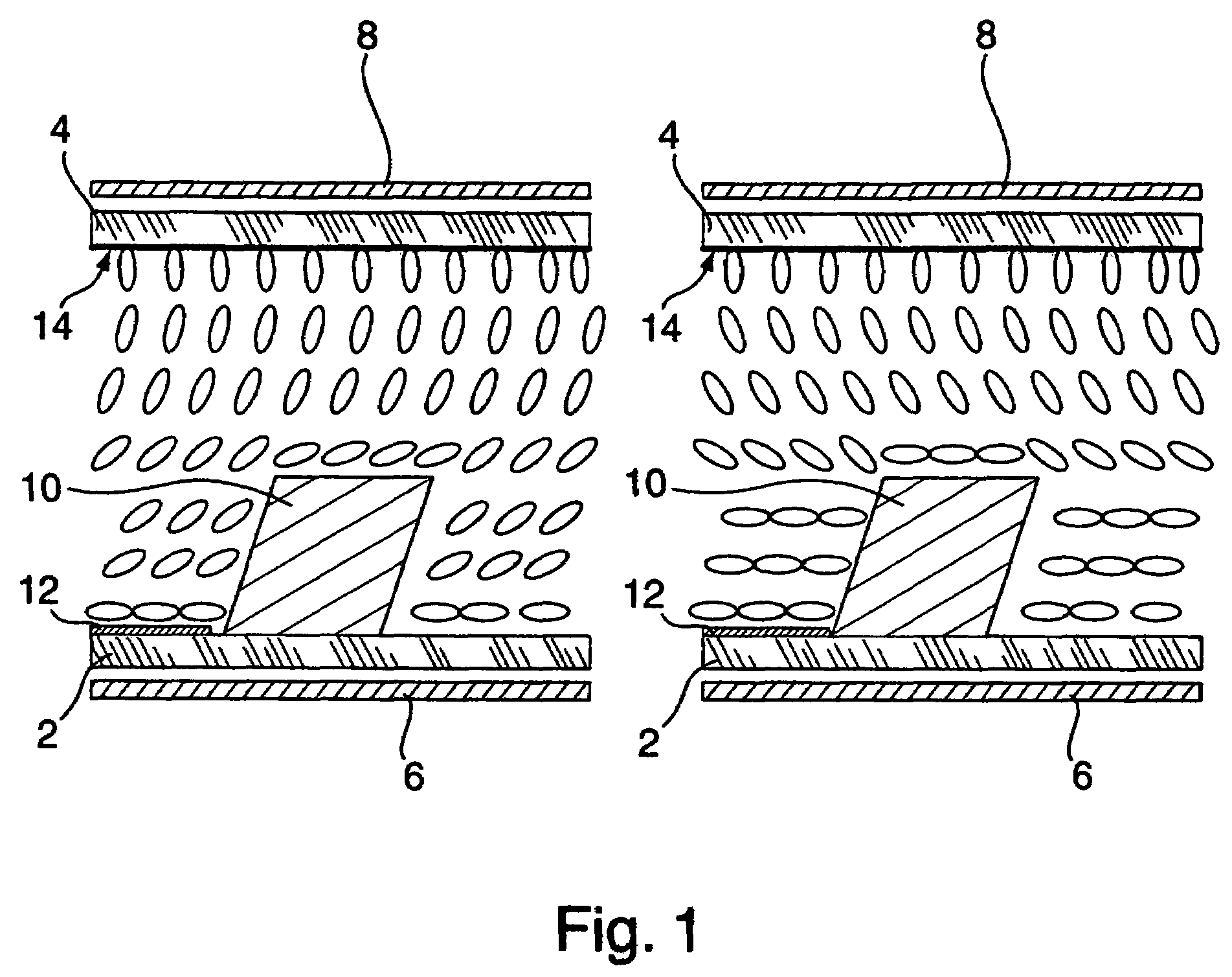
[0043]The bistable cell shown schematically in FIG. 1 is of a type known per se from EP 1 139 151, the content of which is incorporated herein by reference. The cell comprises a first cell wall 2 and a second cell wall 4 which enclose a layer of nematic LC material of negative dielectric anisotropy. The molecules of the LC are represented as ellipses, with the long axis indicating the local director. The inner surface of each cell wall is provided with a transparent electrode pattern, for example row electrodes 12 on the first cell wall 2 and column electrodes 14 on the second cell wall 4, in known manner.

[0044]The inner surface of the first cell wall 2 is textured with an array of square posts 10, and the inner surface of the second cell wall 4 is flat. The posts 10 are approximately 1 μm high and the cell gap is typically 3 μm. The flat surface is treated to give homeotropic alignment. The posts are not homeotropically treated.

[0045]Such an array of square posts has two preferred ...


PUM


Abstract

A liquid crystal device comprises a layer of a liquid crystal material contained between two spaced-apart cell walls with electrodes for applying an electric field across at least some of the liquid crystal material. At least one of the cell walls includes an alignment structure for inducing a desired local orientation of molecules of the liquid crystal material adjacent thereto. The liquid crystal material includes non-polymerisable low molecular weight surfactant molecules. The invention also provides a liquid crystal composition for use in the device and a method of manufacturing the device.

Description

FIELD OF THE INVENTION[0001]The present invention relates to liquid crystal devices, liquid crystal compositions suitable for use in the devices and method of making same.BACKGROUND OF THE INVENTION[0002]Liquid crystal (“LC”) devices typically comprise a pair of opposed, spaced-apart cell walls with LC material between them. The cell walls have transparent electrode structures for applying electric fields to align the LC molecules. There are three main types of LC materials: nematic, cholesteric (chiral nematic) and smectic, all of which find application in different types of LC display. Many different LC display modes are known in the art. A common feature of these display modes is that each requires a surface alignment on at least one of the cell walls to provide an appropriate alignment of the LC director. Prior art display modes and methods of obtaining desired surface alignments are discussed in WO 99 / 18474 and EP 1 139 151. U.S. Pat. No. 3,843,233 describes an alternative to u...

Claims


Application Information

Patent Timeline
IPC IPC(8): C09K19/00C09K19/52G02F1/137C09K19/54C09K19/56G02F1/1333G02F1/1337
CPCC09K19/56Y10S430/165Y10T428/10C09K2323/00
Inventor KITSON, STEPHEN CHRISTOPHERCARTER, NEILCINDEREY, MICHAEL BERNARD
Owner HEWLETT PACKARD DEV CO LP
Why Eureka
Try Eureka