Alternating current driven type plasma display device and production method therefor

a technology of alternating current and display device, which is applied in the manufacture of electrode systems, cold cathode manufacturing, and electric discharge tube/lamp manufacture, etc., can solve the problems of increasing driving voltage, increasing driving voltage, increasing driving voltage, etc., and achieves enhanced discharge stability, time delay of discharge, and enhanced reliability of alternating current driven type plasma display device

Inactive Publication Date: 2008-08-05
SONY CORP
View PDF13 Cites 0 Cited by
  • Summary
  • Abstract
  • Description
  • Claims
  • Application Information

AI Technical Summary

Benefits of technology

[0016]An object, therefore, of the present invention is to provide an alternating current driven type plasma display device which, without increasing a driving voltage (discharge voltage) and, also, without increasing the time delay of discharge, can realize a high efficiency and a low power consumption and, further, a method for producing the alternating current driven type plasma display device.

Problems solved by technology

Although it is possible to enhance the light emission efficiency by increasing a partial pressure of Xe gas of the discharge gas, when the partial pressure of the Xe gas is increased, a problem is caused in that driving voltage (discharge voltage) is increased or a time delay of discharge is increased.
Then, the dielectric layer 14 comprising the glass paste having a low melting point comes to be one cause of the increase of the driving voltage or the increase of the time delay of discharge.
However, when the dielectric layer 14 comprising the glass paste having a low melting point is allowed to be thin, although the driving voltage is decreased, a problem is caused in that change of luminance along the passage of time becomes large.
Further, since the dielectric layer 14 comprising the glass paste having a low melting point has a high specific inductive capacity and a large capacitance, a large amount of current flows, to thereby cause an increase of consumption of current of the plasma display device.
However, in the dielectric layer 14 comprising an ordinary SiOX, the problem of the increase of the time delay of discharge has not been solved.

Method used


Image

  • Alternating current driven type plasma display device and production method therefor
  • Alternating current driven type plasma display device and production method therefor
  • Alternating current driven type plasma display device and production method therefor

Examples


example 1

[0064]Example 1 relates to an alternating current driven type plasma display device according to the present invention (hereinafter, referred to also as “plasma display device” for short) and a production method therefor.

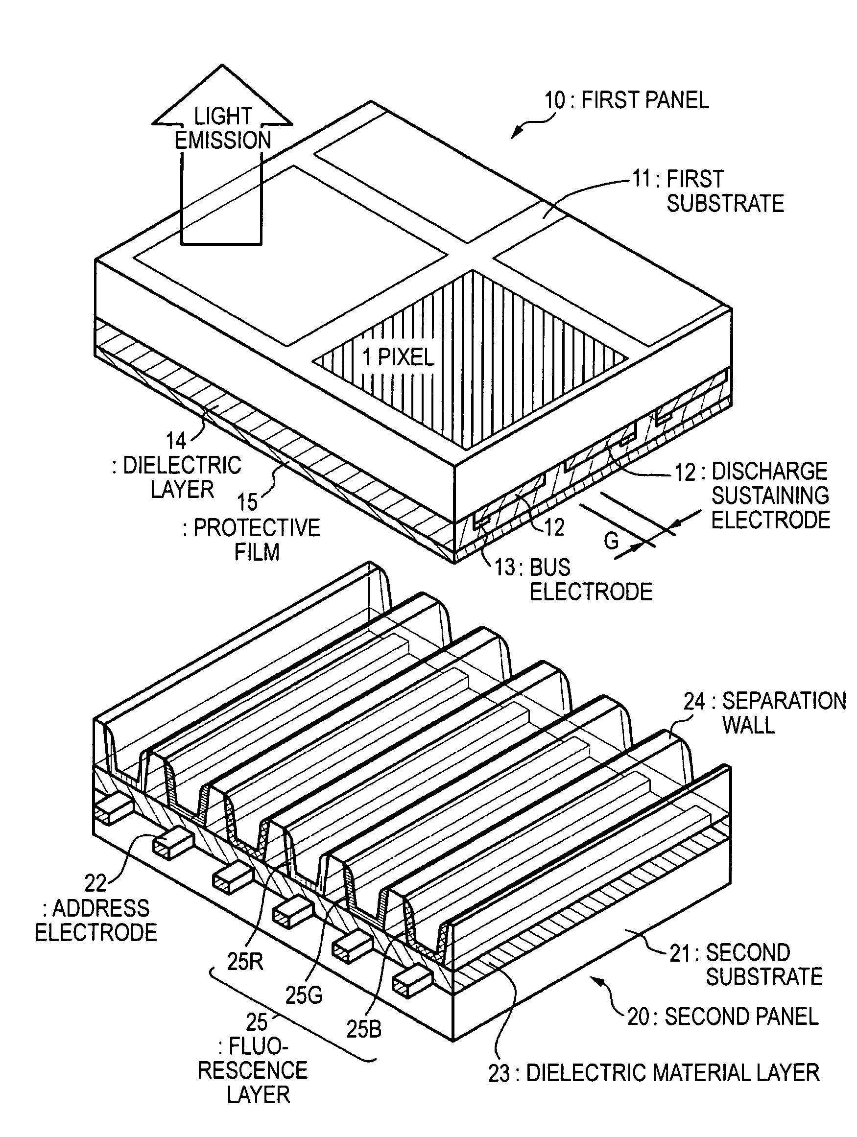
[0065]The plasma display device of Example 1, being a plasma display device of tri-electrode type, comprises a first panel 10 comprising a plurality of first electrodes 12 formed on a first substrate 11 and a dielectric layer 14 formed on the first substrate 11 and the first electrodes 12 and a second panel 20, in which the first panel 10 and the second panel 20 are bonded to each other in circumferential portions thereof. On this occasion, a schematic exploded perspective view of the plasma display device of Example 1 is same as that shown in FIG. 1. Since constitution and structure of this plasma display device are same as those of the plasma display device as described in “BACKGROUND OF THE INVENTION”, detailed description is omitted. Hereinafter, difference from...


PUM


Abstract

An alternating current driven type plasma display device which does not increase a driving voltage (discharge voltage) and does not increase a time delay of discharge is provided. The alternating current driven type plasma display device contains a first panel having a plurality of first electrodes formed on a first substrate and a dielectric layer formed on the first substrate and the first electrodes and a second panel, in which the first panel and the second panel are bonded to each other in circumferential portions thereof, the dielectric layer is constituted by SiOX, and bonding density of H2O contained in SiOX is 3.0×10²⁰ Bonds / cm3 or more.

Description

BACKGROUND OF THE INVENTION[0001]1. Field of the Invention[0002]The present invention relates to an alternating current driven type plasma display device and a method for producing an alternating current driven type plasma display.[0003]2. Description of the Related Art[0004]As an image display device that can be substituted for a currently mainstream cathode ray tube (CRT), flat-screen (flat-panel) display devices are studied in various ways. Such flat-panel display devices include a liquid crystal display (LCD), an electroluminescence display (ELD) and a plasma display device (PDP). Of these, the plasma display device has advantages that it is relatively easy to form a larger screen and attain a wider viewing angle, that it has excellent durability against environmental factors such as temperatures, magnetism and vibrations, and that it has a long lifetime, and so on. The plasma display device is, therefore, expected to be applicable not only to a home-use wall-hung television set...

Claims


Application Information

Patent Timeline
Patent Type & Authority Patents(United States)
IPC IPC(8): H01J17/49H01J9/02H01J9/24H01J11/22H01J11/34H01J11/38H01J17/02
CPCH01J9/02H01J11/38H01J11/12
Inventor KOBAYASHI, ARATA
Owner SONY CORP
Why Eureka
Try Eureka