Three-dimensional electrophoretic displays

a three-dimensional electrophoretic display and display technology, applied in optics, instruments, electrical equipment, etc., can solve the problems of low cost, unadapted 3-d imagery systems and applications, and large power consumption of backlight and color filters, and achieve the effect of low cos

Inactive Publication Date: 2008-08-05
E INK CALIFORNIA
View PDF140 Cites 50 Cited by
  • Summary
  • Abstract
  • Description
  • Claims
  • Application Information

AI Technical Summary

Benefits of technology

[0033]An advantage of the present invention is that the performance of the new stereoscopic display apparatus is not sensitive to viewing angle and environmental lighting condition.
[0034]Another advantage of the present invention is that the new stereoscopic display apparatus and method can be made by either a continuous or batch process at low cost.

Problems solved by technology

Another recent display technology, the electrophoretic display (“EPD”), appears promising but has not been adapted for 3-D imagery systems and applications.
The major disadvantage of this EPD device is that the operation of its backlight and color filters consumes a great deal of power, an undesirable feature for hand-held devices such as PDAs (personal digital assistants) and e-books.
Each of these devices, however, has its problems as noted below.
However, difficulties are encountered in the formation of the partitions, the filling of the display with the fluid, the enclosure of the fluid in the display and the separation of electrophoretic fluids of different colors or polarization properties from each other.
A full color or 3-D image presentation is thus impossible because of the lack of a mechanism to eliminate the undesirable cross-talk due to intermixing of components among the cells.
The use of parallel line reservoirs such as microchannels, microgrooves or microcolumns to form the EPD device has the problem of undesirable particle sedimentation or creaming along the channel or groove direction.
In addition, the lack of a seamless, air-pocket-free and continuous sealing process to enclose the electrophoretic fluid without undesirable intermixing or cross-talk makes the 3-D image or roll-to-roll manufacturing extremely difficult.
This large microcapsule size results in a poor scratch resistance and a slow response time for a given voltage because of the relatively large inter-electrode gap dictated by the relative large capsules.
Also, the hydrophilic shell of microcapsules prepared in an aqueous solution typically results in sensitivity to high moisture and temperature conditions.
However, the microencapsulation process in an aqueous solution imposes a limitation on the type of charge-controlling agents that can be used.
Other drawbacks associated with the microcapsule system include poor resolution and poor addressability for color or 3-D applications because of its large capsule size and broad size distribution.
A conventional display prepared by the edge sealing adhesive method will no longer be functional if the display is cut or a hole is drilled through the display, because the display fluid would leak out.
Without the microcup structure and the seamless sealing processes, it would be very difficult to prevent the fluids in adjacent areas from intermixing or being subject to cross-talk in applications such as full color and 3-D presentations.

Method used


Image

  • Three-dimensional electrophoretic displays
  • Three-dimensional electrophoretic displays
  • Three-dimensional electrophoretic displays

Examples


Embodiment Construction

[0042]Unless defined otherwise in this specification, all technical terms are used herein according to their conventional definitions as they are commonly used and understood by those of ordinary skill in the art.

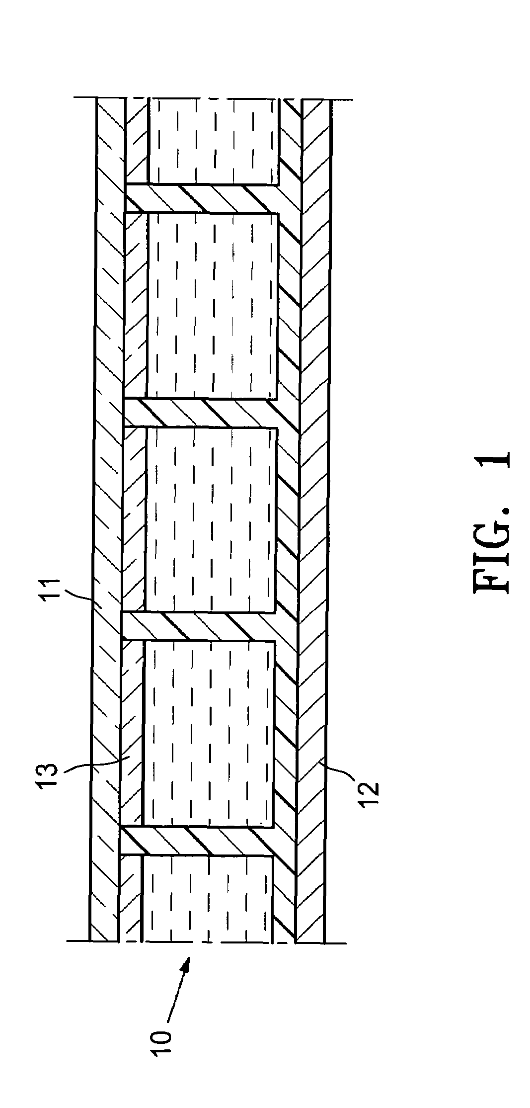
[0043]The term “microcup” refers to the cup-like indentations created by microembossing or imagewise exposure.

[0044]The term “cell”, in the context of the present invention, is intended to mean the single unit formed from a sealed microcup. The cells are filled with an electrophoretic dispersion which may be an optically active electrophoretic dispersion.

[0045]The term “well-defined”, when describing the microcups or cells, is intended to indicate that the microcup or cell has a definite shape, size and aspect ratio which are pre-determined according to the specific parameters of the manufacturing process.

[0046]The term “aspect ratio” is a commonly known term in the art of electrophoretic displays. In this application, it refers to the depth to width or depth to length rati...


PUM

PropertyMeasurementUnit
sizeaaaaaaaaaa
specific gravityaaaaaaaaaa
white coloraaaaaaaaaa

Abstract

This invention relates to three-dimensional (3-D) electrophoretic displays comprising individually sealed cells filled with optically active electrophoretic dispersions, and more particularly to bi-stable, low-power-consumption and sealed microcup-based electrophoretic displays for high-quality three-dimensional imagery applications.

Description

[0001]This application is a continuation-in-part of U.S. application Ser. No. 10 / 243,280, filed Sep. 12, 2002 now abandoned; which claims the benefit of U.S. Provisional Application 60 / 322,173, filed Sep. 13, 2001; and is also a continuation-in-part of U.S. application Ser. No. 09 / 518,488, filed on Mar. 3, 2000 now U.S. Pat. No. 6,930,818; the contents of the above applications are incorporated herein by reference in their entirety.FIELD OF THE INVENTION[0002]This invention relates to three-dimensional electrophoretic displays comprising individually sealed cells filled with an electrophoretic dispersion which may be an optically active electrophoretic dispersion. This invention more particularly relates to bi-stable, low-power-consumption and sealed microcup-based electrophoretic displays for high-quality three-dimensional imagery applications.BACKGROUND OF THE INVENTION[0003]Various techniques have been used in the prior art to record, transmit and display three-dimensional (“3-D”...

Claims


Application Information

Patent Timeline
Patent Type & Authority Patents(United States)
IPC IPC(8): G02B26/00G02F1/00G09G3/34G02B27/22G02F1/1333G02F1/167G02F1/1677H04N13/00
CPCG02B27/22H04N13/0434G02F1/167G02F1/133377H04N13/337G02F1/1677
Inventor LIANG, RONG-CHANGCHEN, DAVID
Owner E INK CALIFORNIA
Why Eureka
Try Eureka