

Built in self test system and method for detecting and correcting cycle slip within a deserializer
- Summary
- Abstract
- Description
- Claims
- Application Information
AI Technical Summary
Benefits of technology
Problems solved by technology
Method used
Image

Examples
Embodiment Construction
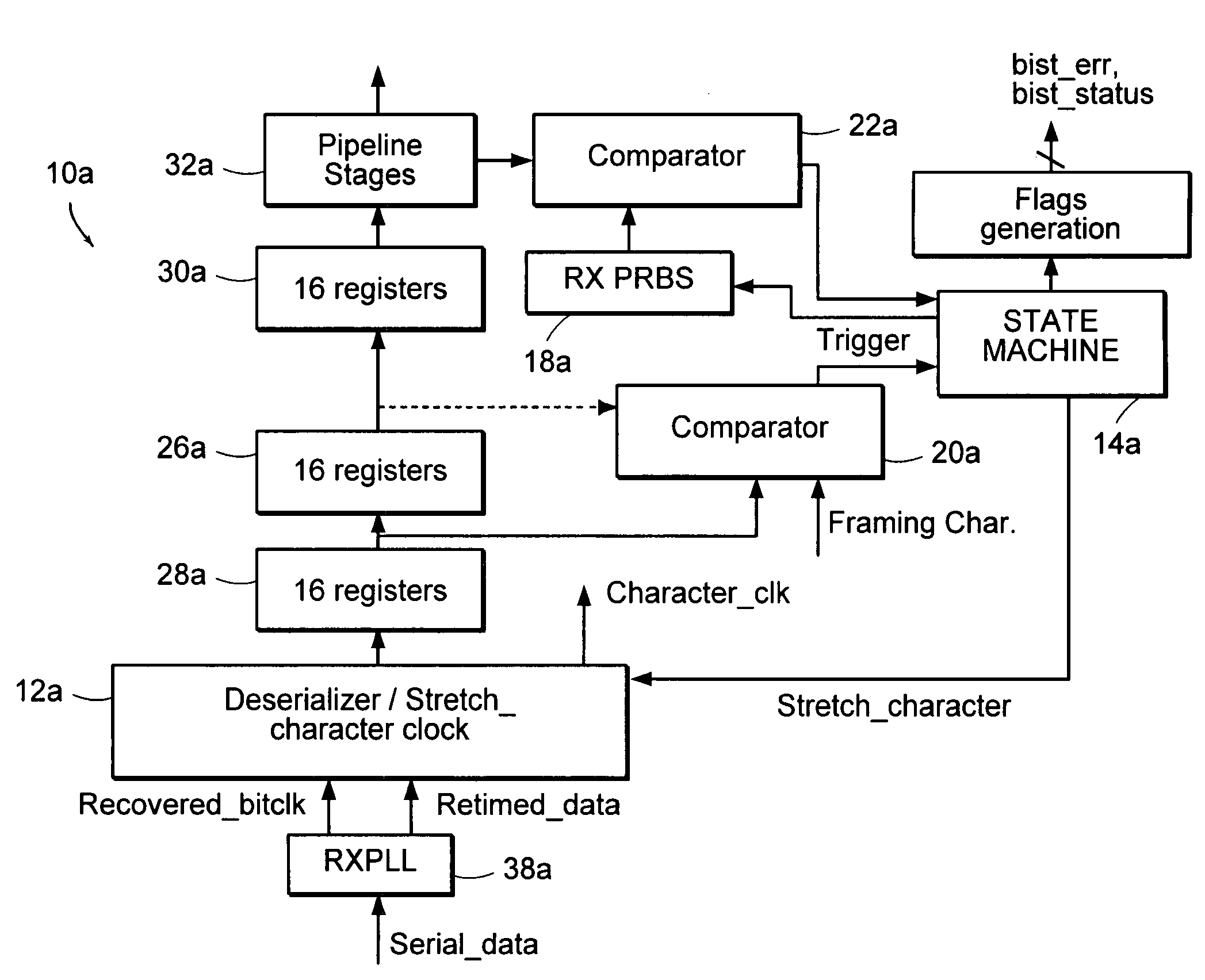
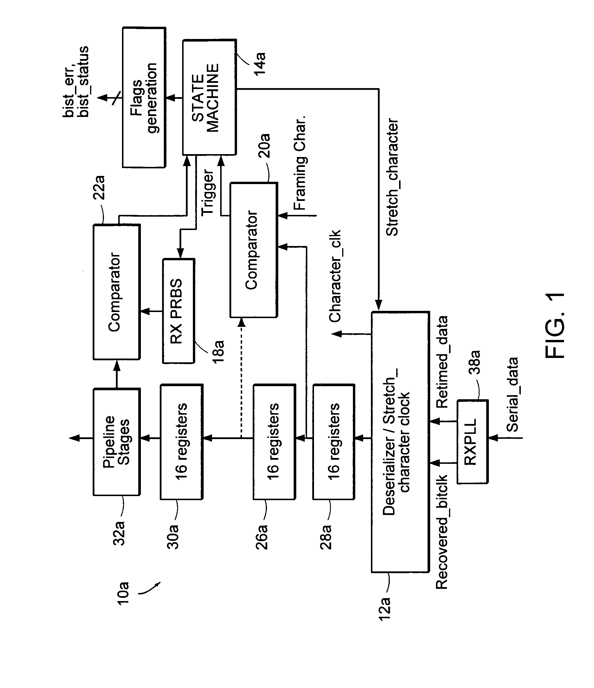
[0039]Turning now to FIG. 1, receiver 10a is shown having a 1-to-N deserializer 12a, and a state machine 14a that controls the deserializer 12a and a frame cycle clock generator within deserializer 12a. Receiver 10a is shown as a physical layer device that performs a deserializing function. As part of the deserialization process, receiver 10a also includes a BIST circuit that tests the functionality of various physical devices, including the transmit and receive phase-locked loops (PLLs), encoders, and decoders, etc. The BIST circuit can also be used to measure AC parameters such as jitter.
[0040]Receiver 10a is shown having three functional blocks. The first block is a bit generator which generates a sequence of pseudo-random bits in the transmitter side, and sends the PRBS across the communication channel to receiver 10a. The same bit sequence that generates the PRBS bits within the transmitter is also generated in the receiver 10, and is shown as block 18a. The choice of this gene...
PUM
 Abstract
Description
Claims
Application Information