Ear-type clinical thermometer

a thermometer and ear-type technology, applied in the field of thermometers, can solve the problems of unstable output voltage, inability to effect precise measurement, and inability to accurately measure the output voltag

Active Publication Date: 2008-08-12
BIO ECHO NET
View PDF25 Cites 328 Cited by
  • Summary
  • Abstract
  • Description
  • Claims
  • Application Information

AI Technical Summary

Benefits of technology

[0015]Preferably, the second high heat insulation member is tapered forwardly and is provided on the distal end with a concave surface. The turning end portion of the thermistor fine lead wire is bridged over the concave surface of the second high heat insulation member to be exposed above the concave surface. The concave surface of the second high heat insulation member is preferably worked by a mirror finish manner. The concave surface has an effect on reflecting infrared rays to the thermistor.
[0016]A heat time constant of the ultrafast responsivity thermistor is preferably 1 second or lower in order to shorten a period of time of measurement.
[0018]According to the present invention, a range of temperature at which the thermistor can maintain a precision is only a range of a body temperature to be measured and it is not necessary to maintain a precision of the thermistor in a whole range of an environmental temperature to be measured, as is the case with a conventional ear-type clinical thermometer using the thermopile. Consequently, the probe of the present invention is not subject to affection of change of environmental temperature (change of temperature during a short period of time), that is, there is no so-called “roasting” phenomenon in the probe. The temperature measuring circuit in the ear-type clinical thermometer of the present invention can be further simplified than a conventional temperature measuring circuit using a thermopile. An assembling work of the ear-type clinical thermometer of the present invention can be facilitated upon a mass production and an external configuration of a clinical thermometer body is not limited, since the probe is a very small size.

Problems solved by technology

Since the thermopile has an unstable sensitivity in individual differences, the output voltage is unstable, even if there is a certain difference of temperature.
However, when the package is subject to an abrupt change of temperature due to an external factor, a difference of temperature will be caused between a head portion of the package and the heat sink of the thermopile and the probe will output an unstable voltage transiently.
In the case where a heat coupling between the cold junction on the thermopile and the thermistor is poor, a difference of temperature is caused and it is impossible to effect a precise measurement.
Since a B constant (resistant temperature characteristics, that is, a constant for indicating a change of a resistant value obtained from temperatures at any two points) is unstable even if any thermistors have the same standard, it is difficult to maintain a precision within a wide range of environmental temperature.
However, an oversize of the metal holder 111 is limited on account of the object being measured.
Although it is easy to adjust the characteristics of the thermistors in the limited range of temperatures, as is the case where the thermistor is used in an electro clinical thermometer, it will be difficult to adjust the characteristics in a wide range of temperatures in the case where the thermistor is used in a clinical thermometer.
A correcting operation of the thermopile will invite a high cost in production.
Consequently, measured values in the conventional ear-type clinical thermometer will be unstable on account of affection of environmental temperatures.

Method used


Image

  • Ear-type clinical thermometer
  • Ear-type clinical thermometer
  • Ear-type clinical thermometer

Examples


Embodiment Construction

[0029]In describing the preferred embodiment of the present invention, reference will be made herein to FIGS. 1 to 7 of the drawings in which like numerals refer to like features of the invention. Features of the invention are not necessarily shown to scale in the drawings.

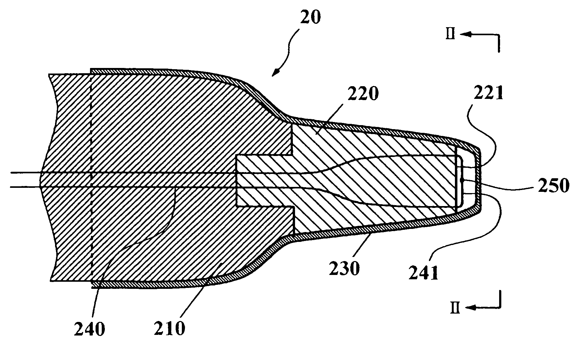
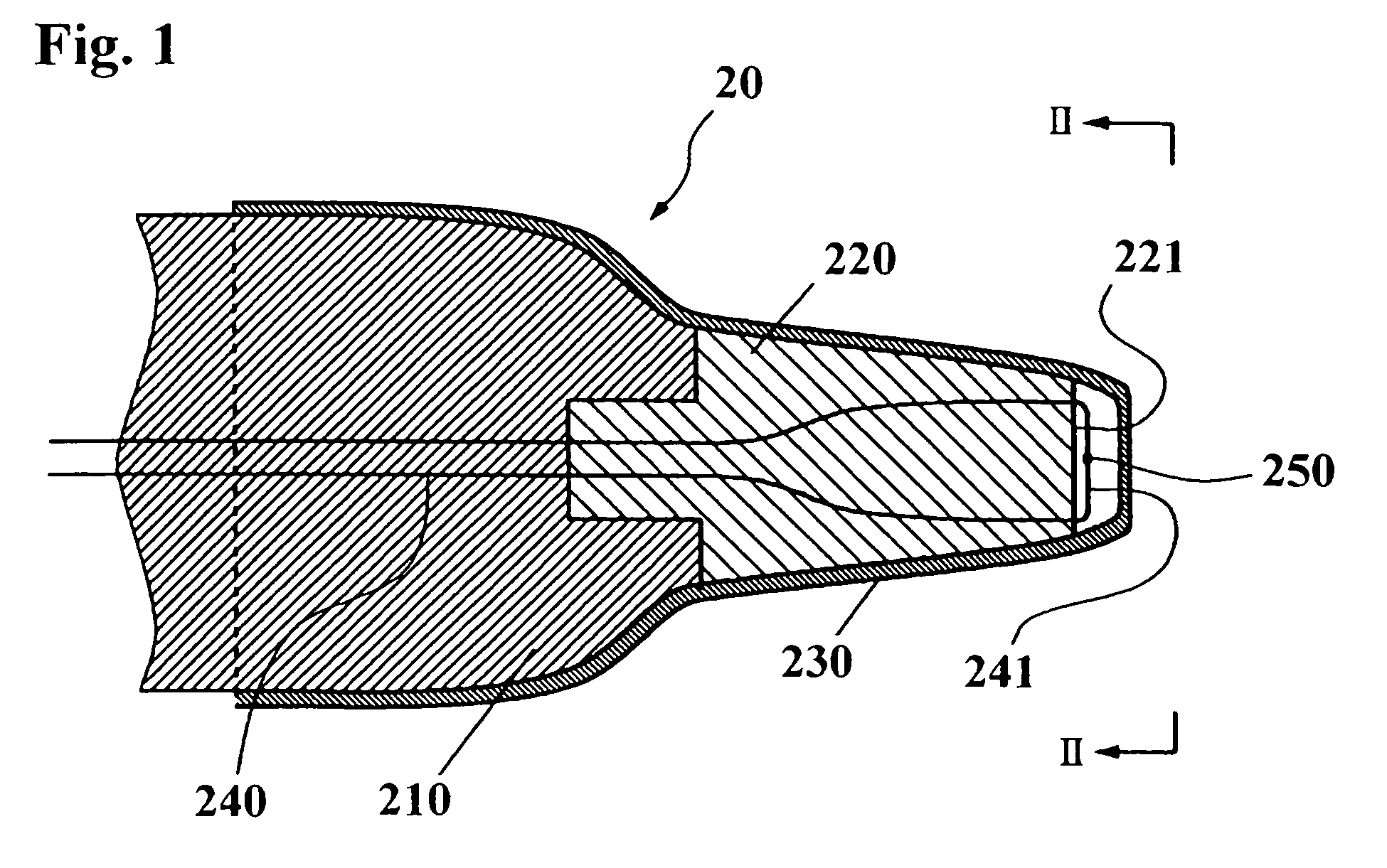
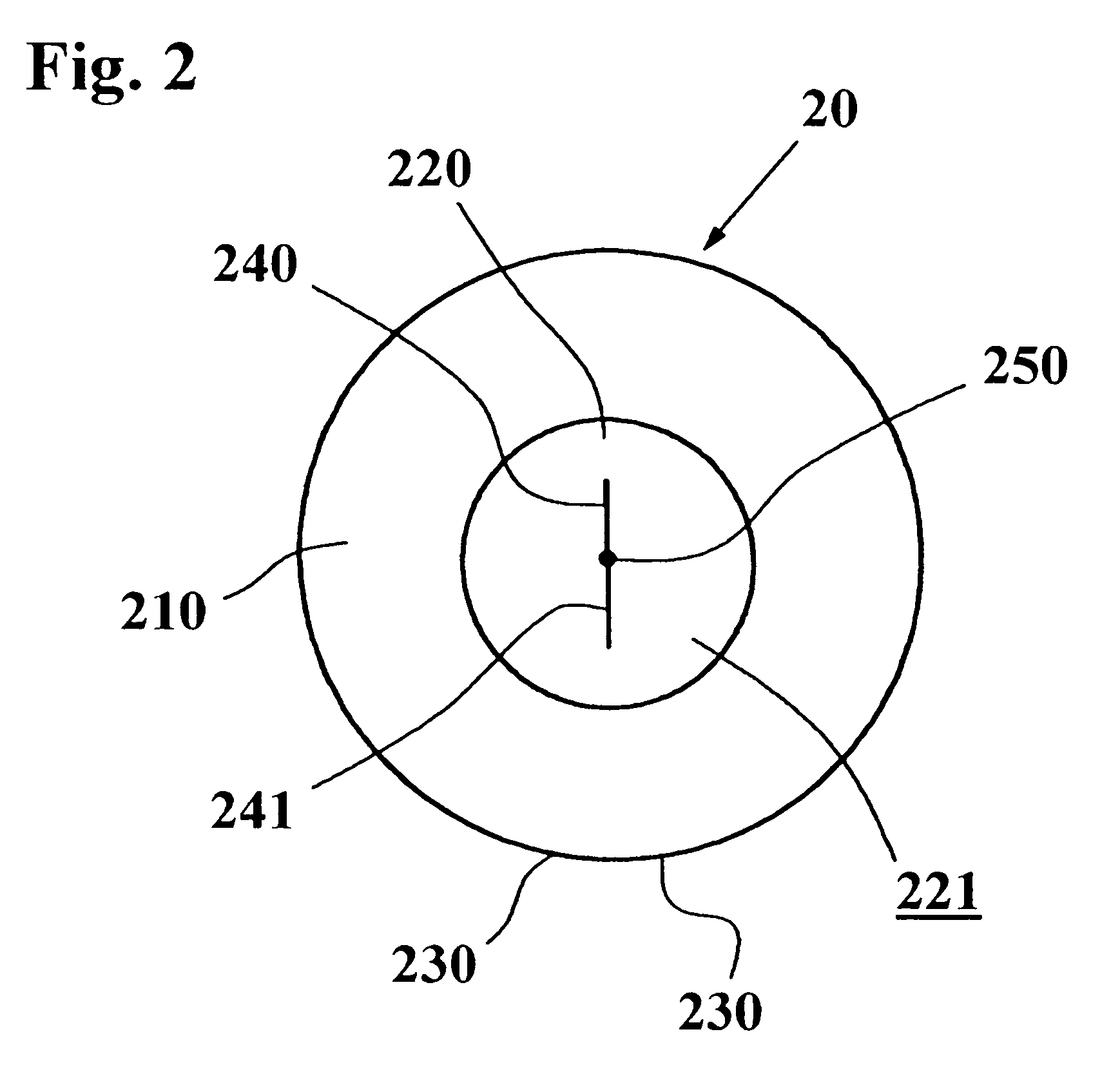
[0030]Referring now to FIGS. 1 to 7, an embodiment of an ear-type clinical thermometer in accordance with the present invention will be explained below. FIGS. 1 and 2 show a structure of a probe 20 in an ear-type clinical thermometer in accordance with the present invention. In the probe 20, a second high heat insulation member 220 made of a resin material is connected to a distal end of a first heat insulation member 210 by conventional coupling means (for example, welding, adhesive, press-fitting, screw-coupling, or the like). The second high heat insulation member 220 is tapered forwardly from a portion coupled to the first heat insulation member 210 to an end surface 221. A protection cover 230 sheathes the fi...


PUM


Abstract

A probe of an ear-type clinical thermometer 20 comprises a first heat insulation member 210 made of a resin material and a second high heat insulation member 220 made of a resin material that is connected to a distal end of the first heat insulation member 210 by conventional coupling means. The second high heat insulation member 220 is tapered forwardly and is provided on the distal end with a concave surface 221. A protection cover 230 sheathes the first heat insulation member 210 and second high heat insulation member 220. A thermistor fine lead wire 240 is embedded in the first heat insulation member 210 and second high heat insulation member 220 so that a turning end portion 241 of the wire 240 is bridged over the concave surface 221 of the second high heat insulation member 220 to be exposed above the concave surface 221. An ultrafast responsivity thermistor 250 is mounted substantially on a center of the turning end portion 241 of the thermistor fine lead wire 240.

Description

BACKGROUND OF THE INVENTION[0001]This invention generally relates to a thermometer that measures a temperature of an object to be measured in a noncontact manner and more particularly relates to a clinical thermometer that measures a temperature of an eardrum by inserting an end of a probe into an ear.[0002]For convenience of explanation, a typical conventional ear-type clinical thermometer will be described below by referring to FIGS. 8 and 9. FIG. 8 is a schematic block diagram of a conventional ear-type clinical temperature, illustrating a principle of operation. FIG. 9 is a longitudinal section view of an end portion of a probe in a typical conventional ear-type clinical thermometer. As shown in FIGS. 8 and 9, a probe 10 of a typical conventional ear-type clinical thermometer utilizes a thermopile 11. In general, a thermopile creates an electric potential difference (Seebeck effect) by a difference of temperature between a cold junction and a hot junction on the thermopile. In o...

Claims


Application Information

Patent Timeline
Patent Type & Authority Patents(United States)
IPC IPC(8): A61B5/00G01J5/20
CPCG01J5/04G01J5/046G01K7/16G01J5/06G01K1/18G01J5/049
Inventor TANAKA, HIDEKI
Owner BIO ECHO NET
Why Eureka
Try Eureka