Detachable aneurysm neck bridge

a neck bridge and aneurysm technology, applied in the field of systems, apparatus and methods for bridging the neck of aneurysms, can solve the problems of high risk of aneurysm occlusion, particularly acute medical risk, and the possibility of a portion of the coil moving out of the aneurysm entrance zone and into the feeding vessel

Inactive Publication Date: 2008-08-12
STRYKER EURO OPERATIONS HLDG LLC +1
View PDF85 Cites 203 Cited by
  • Summary
  • Abstract
  • Description
  • Claims
  • Application Information

AI Technical Summary

Benefits of technology

[0015]In accordance with one aspect of the present invention, a neck bridge for bridging across a neck of an aneurysm comprises a junction region, one or more array elements attached to the junction region, and a cover attached to the junction region. The cover may alternatively be attached to the array elements, or to both the array elements and the junction region. By way of non-limiting examples, the array element may have a shape of a loop, a substantially rectilinear shape, or a curvilinear shape. In preferred embodiments, the array element may be stretched into a delivery shape when positioned within a lumen of a delivery catheter, and assumes an unfolded configuration when unconfined outside the lumen. Suitable materials for construction of the array element include, but are not limited to, elastic and super elastic materials, such as Nitinol.

Problems solved by technology

As noted above, aneurysms present a particularly acute medical risk due to the dangers of potential rupture of the thin vascular wall inherent in such aneurysms.
However, after, or perhaps during delivery of a coil into the aneurysm, there is a risk that a portion of the coil might migrate out of the aneurysm entrance zone and into the feeding vessel.
The presence of the coil in that feeding vessel may cause a highly undesirable occlusion there.
Also, there is a risk that the blood flow in the vessel and aneurysm may induce movement of the coil farther out of the aneurysm, resulting in a more developed embolus in the feeding vessel.
One type of aneurysm, commonly known as a “wide neck” aneurysm, is known to present particular difficulty in the placement and retention of vaso-occlusive coils, because vaso-occlusive coils lacking substantial secondary shape strength may be difficult to maintain in position within an aneurysm no matter how skillfully they are placed.
Also, occluding the parent vessel may not prevent all embolic material migration into the parent vessel.
Further, in certain cases, it is highly undesirable to occlude the parent vessel even temporarily.
Thus, a flow arrest technique is, at times, not effective or even not available as a treatment option.
In some cases, it may still be desirable to deploy vaso-occlusive coils with such a device, but the bulbous body of the vaso-occlusive device may not provide much space within the aneurysm to allow for insertion and deployment of coils.

Method used


Image

  • Detachable aneurysm neck bridge
  • Detachable aneurysm neck bridge
  • Detachable aneurysm neck bridge

Examples


Embodiment Construction

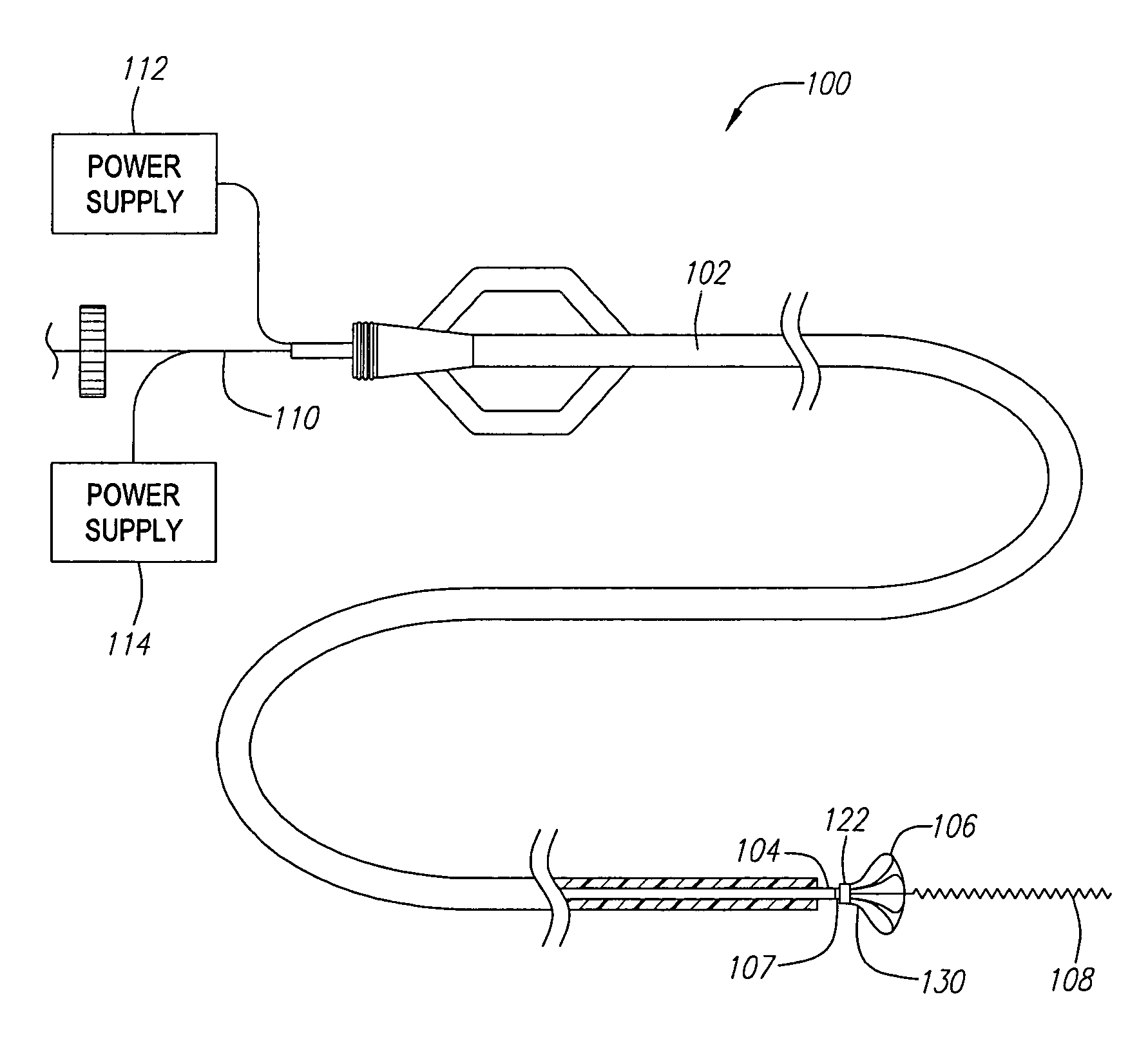
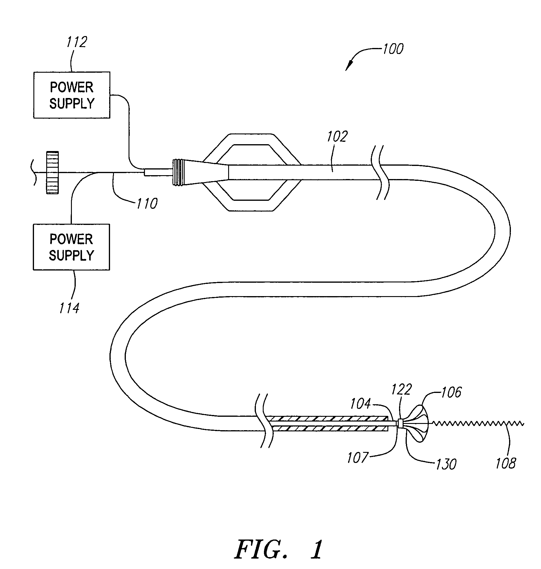
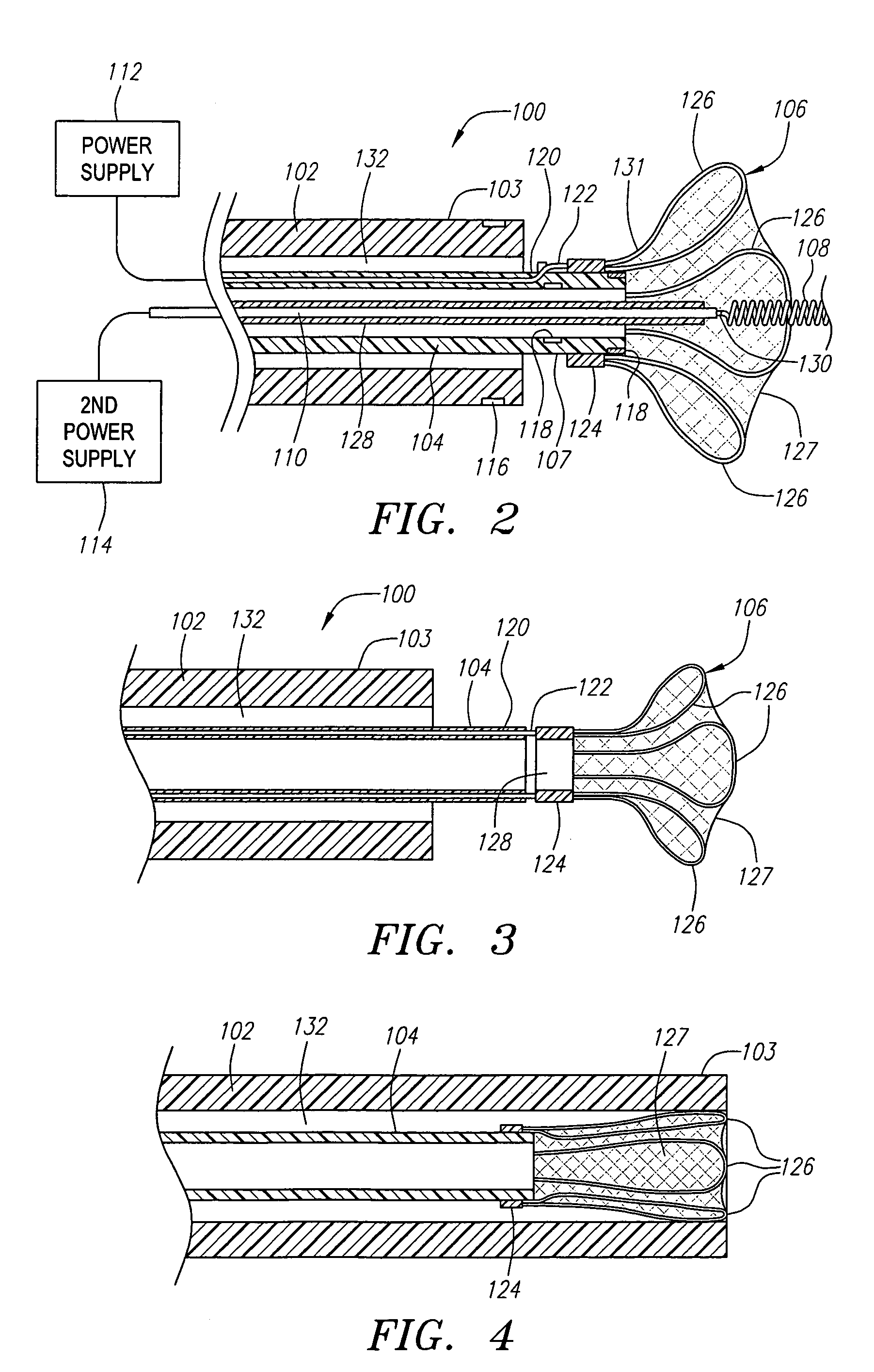
[0043]The disclosed invention relates to devices and procedures for stabilizing the position and, in some instances, the structure of vaso-occlusive devices placed in a target occlusion site, usually an aneurysm. Use of the retaining devices and neck bridges disclosed herein reduce the potential migration of vaso-occlusive devices (e.g., helically wound coils) from target occlusion sites, by forming at least a partial barrier at the entrance zone to the aneurysm, i.e., where the aneurysm meets a feeding vessel.

[0044]FIG. 1 shows an aneurysm treatment system 100, which includes an aneurysm neck bridge 106 constructed in accordance with a preferred embodiment. The aneurysm treatment system 100 also includes a tubular delivery catheter 102, and an inner elongated tubular member 104 slidable within the tubular delivery catheter 102. The aneurysm neck bridge 106 is removably coupled to a distal end 107 of the elongated tubular member 104 via an electrolytically severable joint 122, and i...


PUM


Abstract

In one embodiment, a neck bridge for bridging the neck of an aneurysm includes a junction region, a number of radially extending array elements attached to the junction region, and a cover attached to one or both of the junction region and an array element. The array elements are configured to be positioned within the aneurysm after the neck bridge is deployed from a delivery device. In a second embodiment, the neck bridge includes a junction region and a braided or mesh-like structure secured to the junction region. The braided or mesh-like structure is made from an elastic material.

Description

RELATED APPLICATION DATA[0001]This application is a continuation-in-part of U.S. patent application Ser. No. 09 / 548,644 filed Apr. 13, 2000, now U.S. Pat. No. 7,128,736 which is a continuation of U.S. patent application Ser. No. 09 / 148,411 filed Sep. 4, 1998, now abandoned, the disclosures of which are expressly incorporated by reference herein.FIELD OF THE INVENTION[0002]The inventions disclosed herein pertain to systems, apparatus, and methods for treating aneurysms, and more specifically, to systems, apparatus, and methods for bridging a neck of an aneurysm.BACKGROUND[0003]Various implantable medical devices have been developed for treating a number of ailments associated with body lumens. In particular, occlusive devices have been proven useful in filling vascular aneurysms, which are formed due to a weakening in the wall of an artery. Vascular aneurysms are often the site of internal bleeding and stroke. A variety of different embolic agents are known to be, at least arguably, ...

Claims


Application Information

Patent Timeline
Patent Type & Authority Patents(United States)
IPC IPC(8): A61B17/00A61B17/12A61B19/00
CPCA61B17/12022A61B17/12113A61B17/1214A61B17/12172A61B17/12168A61B2017/12063A61B19/54A61B2017/1205A61B90/39
Inventor MURPHY, RICHARDWALLACE, MICHAEL P.TRAN, TRINGUYEN, KIMHO, HANHDOAN, MYABRAMS, ROBERT M.CARRISON, HAROLD F.
Owner STRYKER EURO OPERATIONS HLDG LLC
Why Eureka
Try Eureka