Aneurysm plugging device

A blocking device and aneurysm technology, applied in the field of medical devices, can solve the problems of incomplete blocking of the neck of the aneurysm, occlusion of branch vessels, residual coils, etc. Effect

Active Publication Date: 2021-07-09
MICROPORT NEUROTECH SHANGHAI
View PDF16 Cites 4 Cited by
  • Summary
  • Abstract
  • Description
  • Claims
  • Application Information

AI Technical Summary

Problems solved by technology

[0007] In view of the above-mentioned shortcomings of the prior art, the purpose of the present invention is to provide a device for aneurysm closure, which is used for the healing of aneurysms, and overcomes the inability to completely block the neck of the aneurysm caused by the existing coil packing method, and the remaining coils, etc. problems, and the limitations of dense mesh stents and covered stent interventions that can easily lead to branch vessel occlusion

Method used


Image

  • Aneurysm plugging device
  • Aneurysm plugging device
  • Aneurysm plugging device

Examples


Embodiment 1

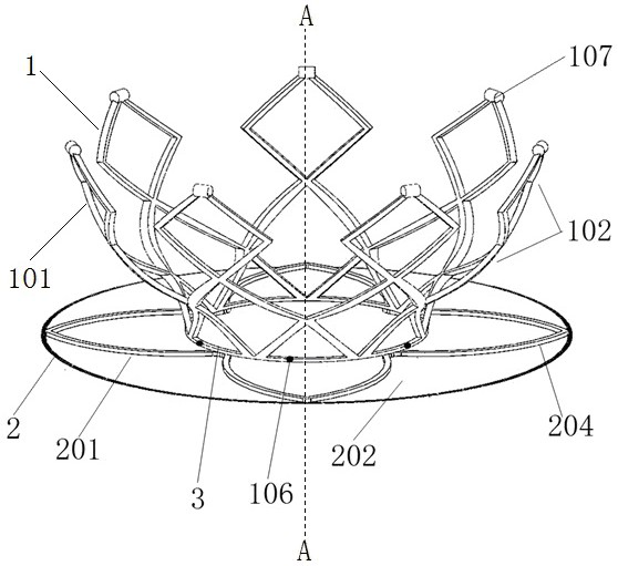
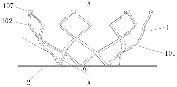
[0053] Such as figure 1 The illustrated scaffold 101 comprises at least four wave-shaped struts 102 arranged around the central axis A-A of the aneurysm occlusion device. Each of the wave-shaped support rods 102 includes at least two waves arranged along the axial direction of the aneurysm occlusion device, wherein the wave form at the bottom end is the same as the wave form at the bottom end of the adjacent wave-shaped support rods 102 connect. Preferably, the waveform at the bottom of each of the wave support rods 102 is connected to the waveform at the bottom of the adjacent wave support rods 102 through contacts, and at least the bottom of the wave support rods 102 The waveform at the top is separated from the waveform in the adjacent waveform support rod 102 , so that the support frame 101 has a bowl-shaped structure with a flared top.

[0054] In this embodiment, there are contacts between the bottommost waveforms of adjacent waveform support rods 102, which can play a...

Embodiment 2

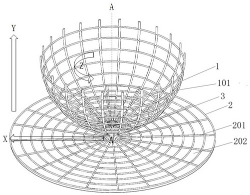
[0067] Such as Figure 3-4 As shown, the support frame 101 includes a flaring top structure formed by weaving metal wires. The braiding of the support frame 101 in this embodiment may be hand-weaving or machine-weaving, and the axial dimension and / or circumferential dimension of the weaving mesh is 0.5mm-1.5mm. Wherein, the axial direction refers to the direction parallel to the central axis A-A of the aneurysm occlusion device (such as Figure 3-4 Y axis in ), the circumferential direction refers to the circumferential direction of rotation around the central axis A-A of the aneurysm occlusion device (such as Figure 3-4 in the Z direction). The bottom end of the support frame 101 is fixed on the intermediate ring 3 , and at least 20 mm of loose yarn is reserved for weaving the skeleton 201 of the blocking part 2 . In this embodiment, the skeleton 201 is woven into a disc-shaped structure, and the radial size of the mesh of the skeleton 201 is 0.1 mm-0.5 mm. Wherein, the ...

Embodiment 3

[0072] Such as Figure 5-6 As shown, the support frame 101 of this embodiment includes a closed cavity structure formed by weaving metal wires. In this embodiment, the closed cavity structure is shaped into a spherical shape. In other embodiments, according to the shape of the aneurysm to be embolized , the support frame 101 may also be shaped as a closed cavity structure in the shape of an ellipsoid, an egg, a lantern, or a spheroid. The weaving of the support frame 101 in this embodiment may be hand weaving or machine weaving, and the axial dimension and / or circumferential dimension of the mesh formed by weaving is 0.5mm-1.5mm. Wherein, the axial direction refers to the direction parallel to the central axis A-A of the aneurysm occlusion device (such as Figure 5-6 Y axis in ), the circumferential direction refers to the circumferential direction of rotation around the central axis A-A of the aneurysm occlusion device (such as Figure 5-6 in the Z direction). The bottom e...


PUM


Abstract

The invention relates to an aneurysm plugging device, which comprises a supporting part and a plugging part. The supporting part comprises a supporting frame, and the diameter of the bottom end of the supporting frame is smaller than the maximum diameter of the supporting frame; the plugging part comprises a framework, and the framework is fixed to the bottom end of the supporting frame. Compared with an existing spring ring packing method, the blood can be immediately prevented from entering the aneurysm, the effects of improving hemodynamic force at the aneurysm neck and promoting aneurysm healing are achieved, and treatment of ruptured aneurysm is particularly facilitated. Compared with an existing dense net stent or covered stent intervention method, the method only aims at covering the arterial aneurysm neck opening, the blood flow of collateral vessels is not affected, and the problem of local ischemia caused by the dense net stent or covered stent intervention method is solved.

Description

technical field [0001] The invention relates to the technical field of medical instruments, in particular to an aneurysm blocking device. Background technique [0002] With the rapid development of my country's national economy, while people's material living standards are improving day by day, factors such as unhealthy living habits and population aging process continue to accelerate, causing cardiovascular and cerebrovascular diseases to become common diseases that seriously threaten people's lives and health. trend. According to the statistics of the World Health Organization, the number of deaths due to cardiovascular and cerebrovascular diseases in my country is as high as 3 million each year, accounting for 51% of the total annual death causes in my country. The number of people who die from cardiovascular and cerebrovascular diseases is as high as 15 million every year in the world, ranking first among various causes of death. [0003] Intracranial Aneurysm (IAN) is ...

Claims


Application Information

Patent Timeline
Patent Type & Authority Applications(China)
IPC IPC(8): A61B17/12
CPCA61B17/12113A61B17/12177
Inventor 张涵孟繁鹤田浩苗琳莉
Owner MICROPORT NEUROTECH SHANGHAI
Why Eureka
Try Eureka