Directional microwave applicator and methods

a microwave applicator and directional technology, applied in the field of microwave antennas, can solve the problems of limited use of antennas, lack of sufficient room for an aperture large enough to provide antenna directionality, etc., and achieve the effect of providing a single conductor

Active Publication Date: 2008-08-12
NASA
View PDF23 Cites 30 Cited by
  • Summary
  • Abstract
  • Description
  • Claims
  • Application Information

AI Technical Summary

Benefits of technology

[0039]In one preferred embodiment, the waveguide conductors and the one or more antenna elements comprise substantially continuous second and third ground conductors which extend along

Problems solved by technology

Within the small confines of a small diameter catheter or a syringe, there is seldom sufficient room for an aperture large enough to provide antenna directionality.
This can be disadvantageous in many instances, as discusse

Method used


Image

  • Directional microwave applicator and methods
  • Directional microwave applicator and methods
  • Directional microwave applicator and methods

Examples


Embodiment Construction

[0067]A miniature directional microwave antenna in accord with the present invention has various medical applications such as, but not limited to, a microwave angioplasty system, a microwave-based hyperthermia treatment system to replace or supplement vertebroplasty, a microwave treatment system for prostate tumors where need for directional heating is required within small confines, and / or for use in biological sterilization applications. Because of the small diameter, circumference, or periphery, the present invention may also be used as a catheter, syringe, and / or cannula antenna. The present invention may also be used for sterilization in regions that would otherwise be difficult to access. Terms such as catheter, syringe, and cannula, or any other means for insertion into tissue, may be utilized herein interchangeably.

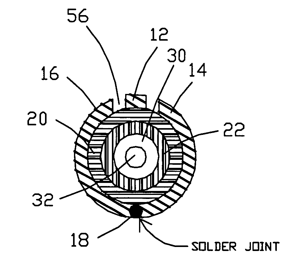
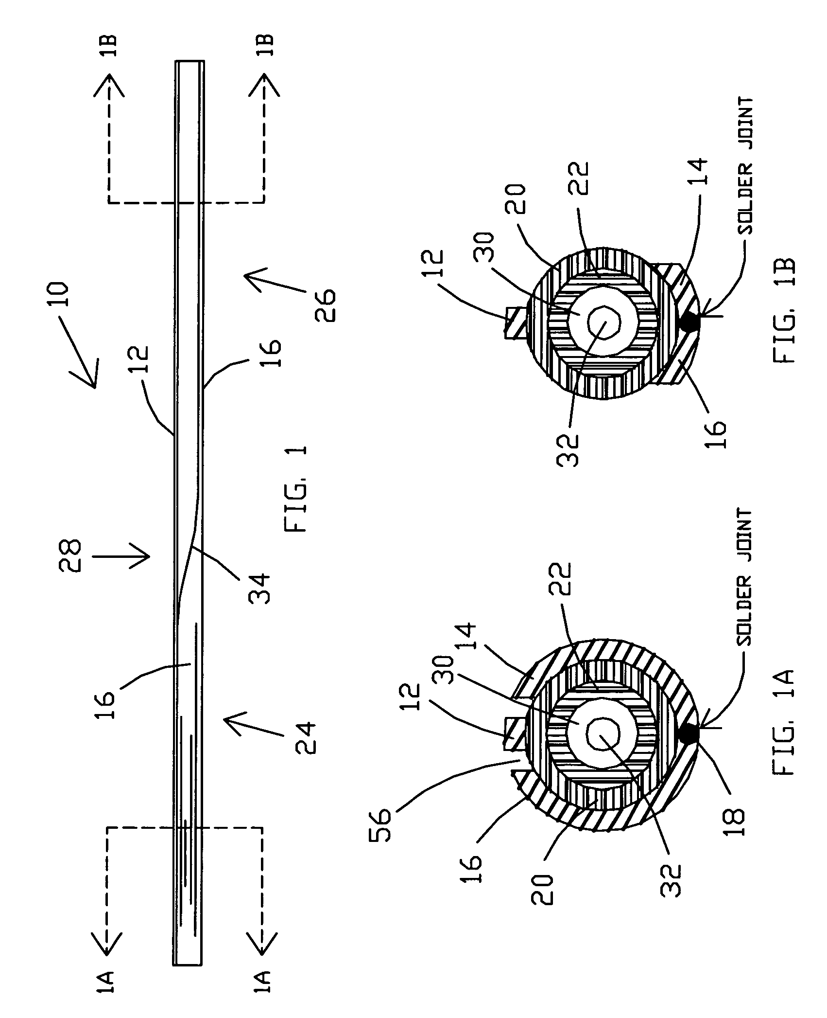
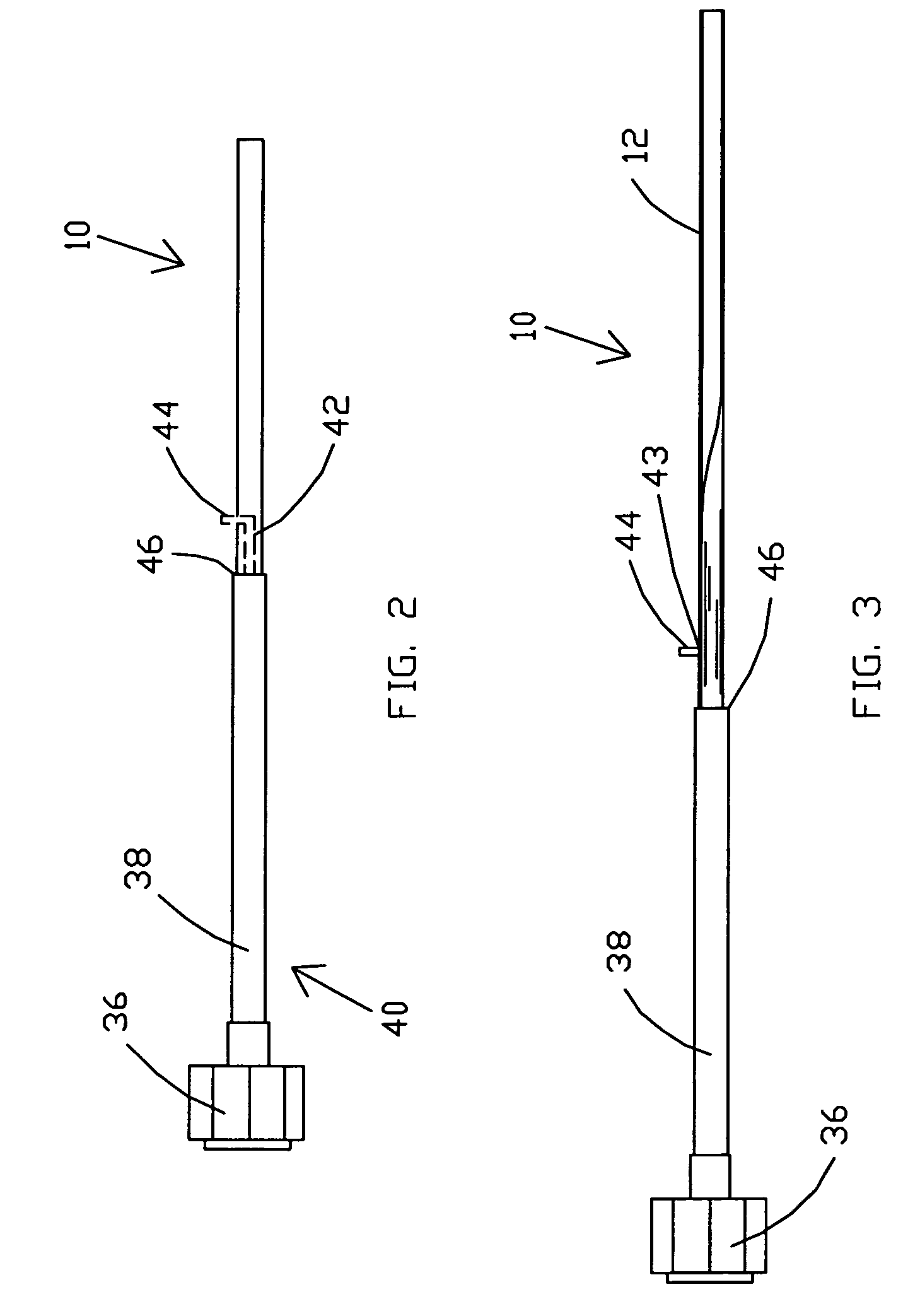
[0068]Referring now to the drawings, and more specifically to FIG. 1, FIG. 1A and FIG. 1B, there is shown an embodiment of a microwave applicator 10 in accord wit...


PUM


Abstract

A miniature microwave antenna is disclosed which may be utilized for biomedical applications such as, for example, radiation induced hyperthermia through catheter systems. One feature of the antenna is that it possesses azimuthal directionality despite its small size. This directionality permits targeting of certain tissues while limiting thermal exposure of adjacent tissue. One embodiment has an outer diameter of about 0.095″ (2.4 mm) but the design permits for smaller diameters.

Description

ORIGIN OF THE INVENTION[0001]The invention described herein was made in the performance of work under a NASA contract and is subject to the provisions of Section 305 of the National Aeronautics and Space Act of 1958, Public Law 85-568 (72 Stat. 435; 42 U.S.C. 2457).BACKGROUND OF THE INVENTION[0002]1. Field of the Invention[0003]The present invention relates generally to microwave antennas and, more specifically, to a miniaturized directional microwave antenna for microwave therapy purposes that is highly suitable for use in catheters or syringes where limited space is available.[0004]2. Description of Prior Art[0005]Microwaves are utilized in various medical treatments. As one possible example, microwave ablation therapy may be utilized to treat damaged heart tissues or other tissues containing malignant or harmful cells. During microwave ablation treatments, the damaged tissue to be ablated may be located in one azimuthal direction with respect to the antenna whereas healthy tissue...

Claims


Application Information

Patent Timeline
IPC IPC(8): A61B18/04A61N1/06
CPCA61B18/12A61B18/1815A61B18/18A61B2018/183
Inventor FINK, PATRICK W.LIN, GREG Y.CHU, ANDREW W.DOBBINS, JUSTIN A.ARNDT, G. DICKEYNGO, PHONG H.
Owner NASA
Why Eureka
Try Eureka