
High flow rate dialysis catheters and related methods

Inactive Publication Date: 2008-08-12
ANGIODYNAMICS INC
View PDF287 Cites 40 Cited by
  • Summary
  • Abstract
  • Description
  • Claims
  • Application Information

AI Technical Summary

Benefits of technology

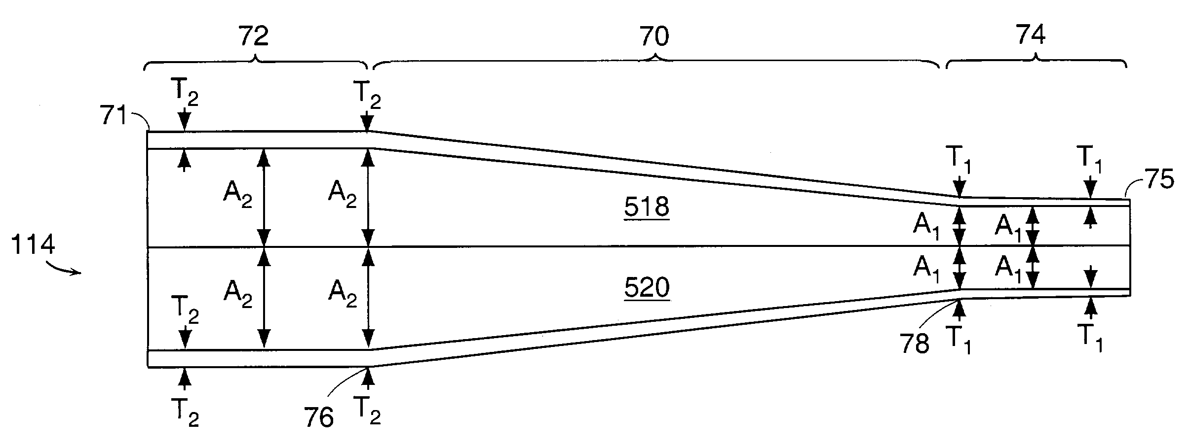
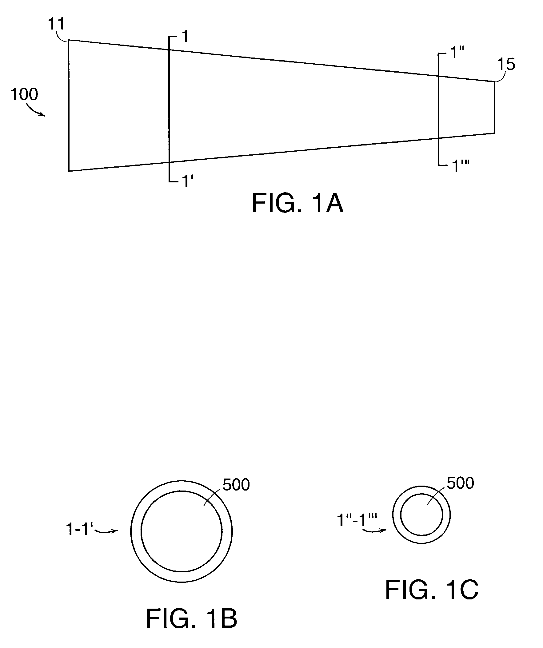
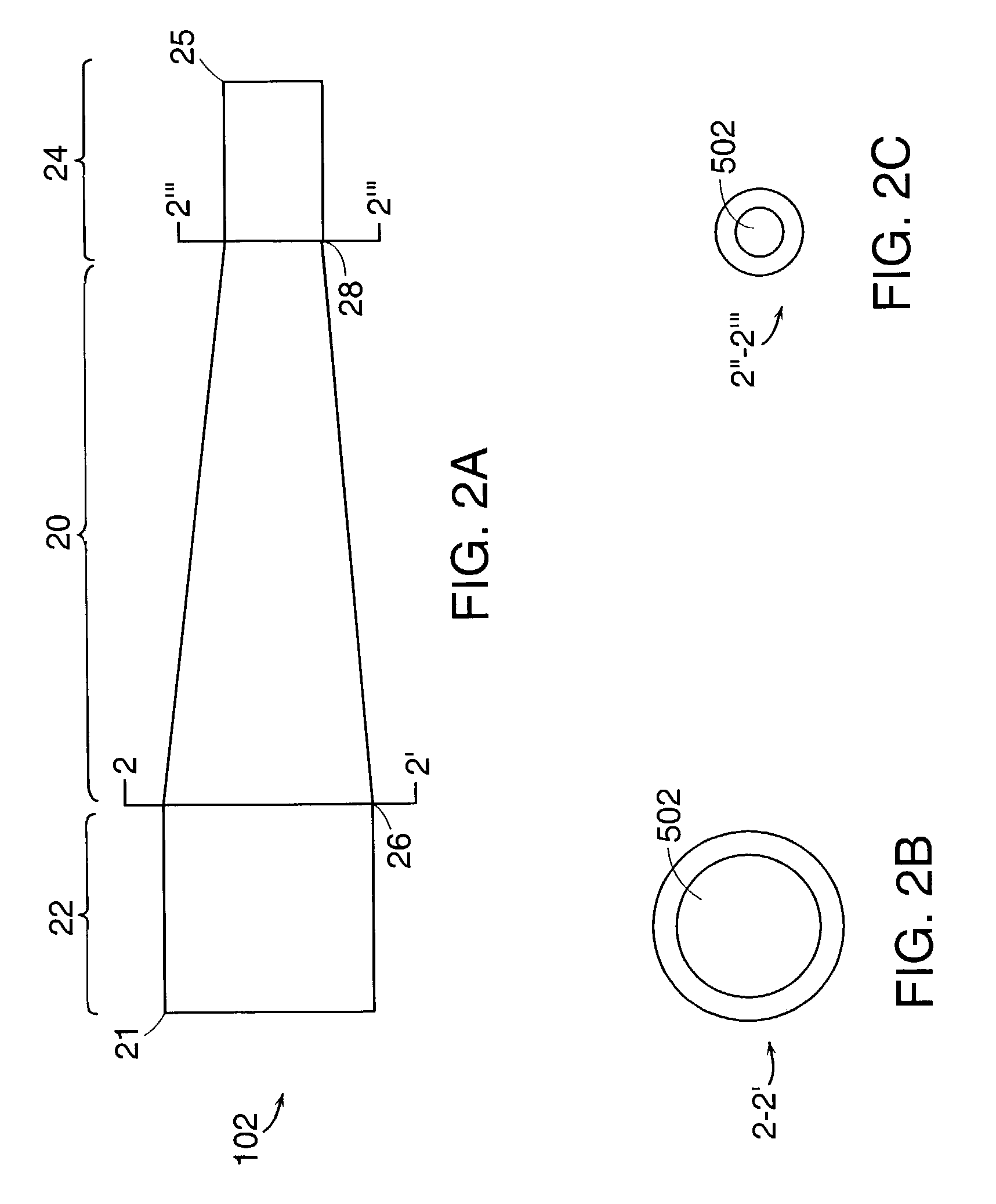
[0005]It has been discovered that one can maximize the flow rate though a catheter despite design constraints of maximal catheter outer diameter (“french size”) and bounded allowable pressure drop. In catheter designs of the present invention, one can tailor a catheter's internal geometry, the thickness of a catheter's wall and internal divider, and / or the ability of a catheter's internal divider to resist flexure when exposed to a pressure gradient in order to reduce resistance to flow, reduce the catheter's tendency to kink, and maximize flow rate. These design concepts are applicable equally to single lumen catheters, dual lumen catheters, or multiple lumen catheters. Also, the presence of a particular tip geometry at the entrance to at least one lumen minimizes the catheter's tendency to become suctioned against the vessel wall and ensures high flow rate.

Problems solved by technology

Both the physiology of blood and the designs of conventional catheters limit flow rate.
Blood cells cannot survive high pressure differentials or excessive mechanical shear.
Conventional catheters have a design which, while useful, does not maximize flow rate within the bounds of these physiological constraints.
Additionally, conventional catheter designs have several other disadvantages.
Second, a shaft of a conventional catheter is prone to kinking, again reducing flow.
Third, an internal septum that divides multiple lumens within a catheter is prone to deflection due to pump pressure.

Method used


Image

  • High flow rate dialysis catheters and related methods
  • High flow rate dialysis catheters and related methods
  • High flow rate dialysis catheters and related methods

Examples


Embodiment Construction

MIDDLE SECTIONDISTAL SECTIONLENGTH (CM)LENGTH (CM)LENGTH (CM)16.0 MIN5.0 ± 1.516.0 MIN

[0066]III. Tip Design

[0067]Catheter designs of the present invention provide for tip designs of a catheter that minimize the possibility of restricted flow into the catheter due to contact between a catheter and a vessel. Referring to FIGS. 3A and 3B, an embodiment of the invention is shown with a tip configuration. This configuration includes a “fin-shaped” distal appendage 202 between a notch 200 and the physical end of the conduit 37. Referring to FIGS. 5A and 5D, another embodiment of the invention is shown with another tip configuration. This embodiment also includes a “trapezoidal” distal appendage 212 between a notch 210 and the physical end of the conduit 47.

[0068]FIG. 9 shows another embodiment of the invention with a tip configuration including a distal appendage 222 between a notch 220 and the physical end of the conduit 57 that is positioned against a vessel wall. Note that the distal a...


PUM

PropertyMeasurementUnit
Luminous fluxaaaaaaaaaa
Thicknessaaaaaaaaaa
Sizeaaaaaaaaaa

Abstract

High flow rate catheters, and related methods, are useful in dialysis and other procedures. A catheter according to the invention comprises a hub and a generally elongated conduit. The conduit has a substantially continuous and smooth wall. The conduit also defines at least one lumen and has a length extending from a proximal end to a distal end of the conduit. The proximal end is coupled to a hub and the distal end has an opening in communication with the lumen. The conduit has a conical shape which tapers along the length.

Description

CROSS-REFERENCE TO RELATED APPLICATION[0001]This application is a divisional of U.S. Ser. No. 09 / 859,090, filed on May 16, 2001, which is a continuation of U.S. Ser. No. 09 / 256421, filed on Feb. 23, 1999, now U.S. Pat. No. 6,280,423, which claims priority to and the benefit of U.S. Ser. No. 60 / 075,724, filed Feb. 24, 1998. The entire disclosures of each of these of these applications are incorporated herein by reference.TECHNICAL FIELD[0002]This invention relates to catheter designs and methods of positioning and making catheter designs. More particularly, the invention relates to catheter designs that increase flow through a catheter as well as methods for positioning a catheter of these designs and making a catheter of these designs.BACKGROUND OF THE INVENTION[0003]Dialysis procedures, for example, frequently use dual lumen catheters to transport blood from a patient to a dialysis machine and then return processed blood back to the patient. See, e.g., McIntosh et al., JAMA 169(8):...

Claims


Application Information

Patent Timeline
IPC IPC(8): B29C47/92B29C47/00D01D5/20D01D5/24A61M25/00B29C48/92
CPCA61M25/0021A61M1/30A61M25/0029A61M25/0009A61M2025/0031A61M2025/0037A61M2025/0293
Inventor DAVEY, CHRISTOPHER T.SANSOUCY, MICHAEL R.MCCARTHY, MATTHEW N.
Owner ANGIODYNAMICS INC
Learn More