Split torque gearbox for rotary wing aircraft with translational thrust system

a technology of rotary wing aircraft and thrust system, which is applied in mechanical equipment, transportation and packaging, and gearboxes. it can solve the problems of blade approaching stall, slow airflow velocity across the retreating blade, and the retreating blade stalling at high forward airspeed, so as to reduce the system weight, minimize vibration, and minimize vibration

a technology of rotary wing aircraft and thrust system, which is applied in mechanical equipment, transportation and packaging, and gearboxes. it can solve the problems of blade approaching stall, slow airflow velocity across the retreating blade, and the retreating blade stalling at high forward airspeed, so as to reduce the system weight, minimize vibration, and minimize vibration

US7413142B2Inactive Publication Date: 2008-08-19SIKORSKY AIRCRAFT CORP

Image

  • Split torque gearbox for rotary wing aircraft with translational thrust system
  • Split torque gearbox for rotary wing aircraft with translational thrust system
  • Split torque gearbox for rotary wing aircraft with translational thrust system

Examples


Embodiment Construction

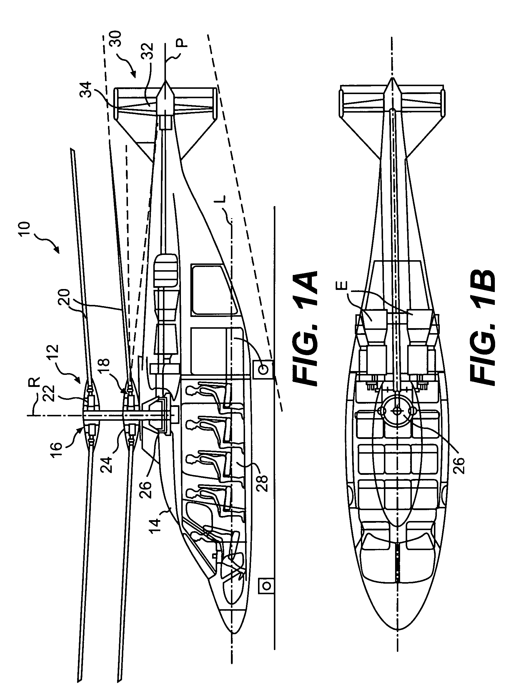
[0020]FIGS. 1A-1B illustrate a vertical takeoff and landing (VTOL) high speed compound rotary-wing aircraft 10 having a dual, countra-rotating, coaxial rotor system 12. The aircraft 10 includes an airframe 14 which supports the dual, counter rotating, coaxial rotor system 12 as well as a translational thrust system 30 to provide translational thrust generally parallel to an aircraft longitudinal axis L. It should be understood that other aircraft configurations will benefit from the present invention.

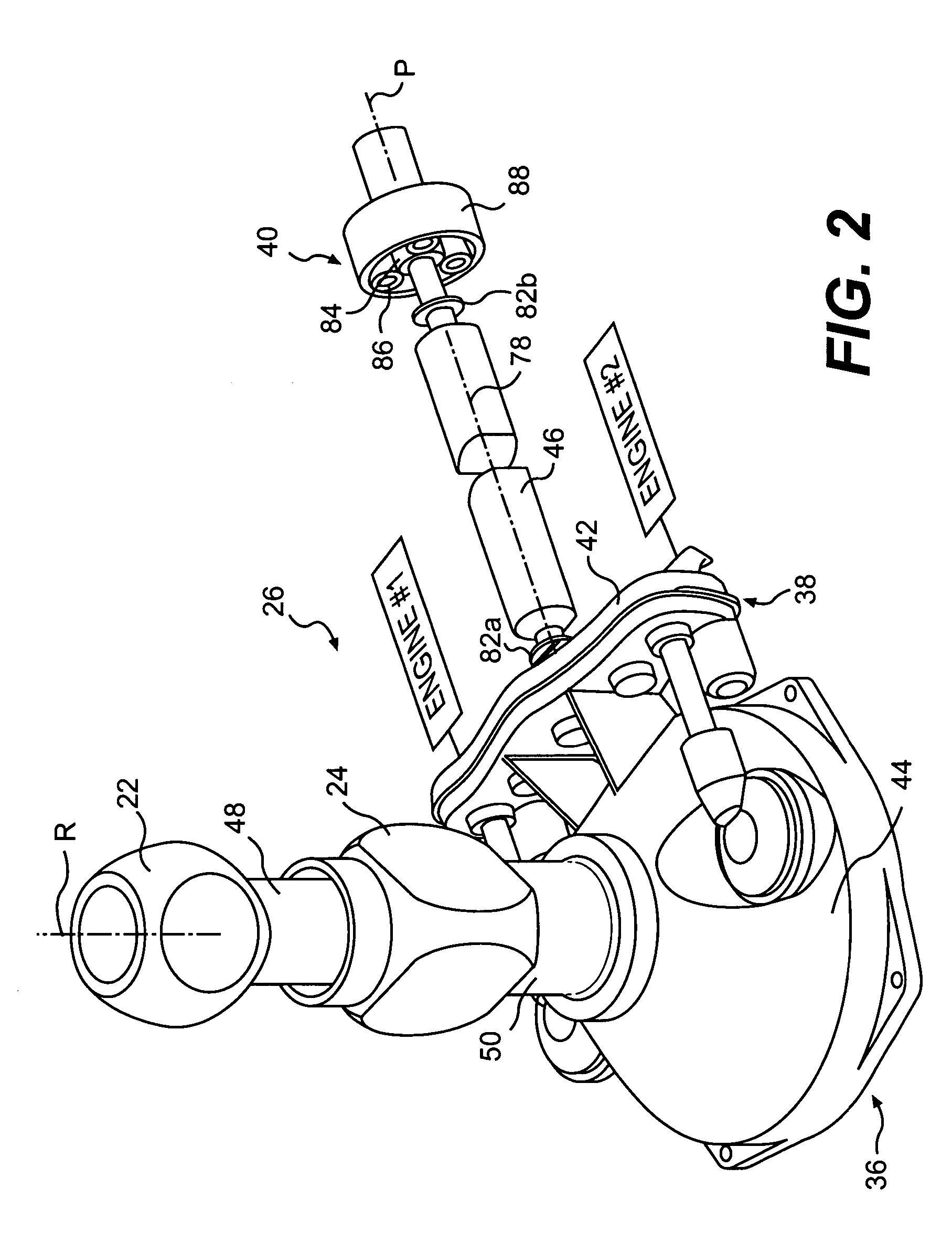
[0021]The rotor system 12 includes a first rotor system 16 and a second rotor system 18 each rotor system 16, 18 includes a multiple of rotor blades 20 mounted to a rotor hub 22, 24. The rotor system 12 is powered by a main gearbox 26 which is preferably located above the aircraft cabin 28.

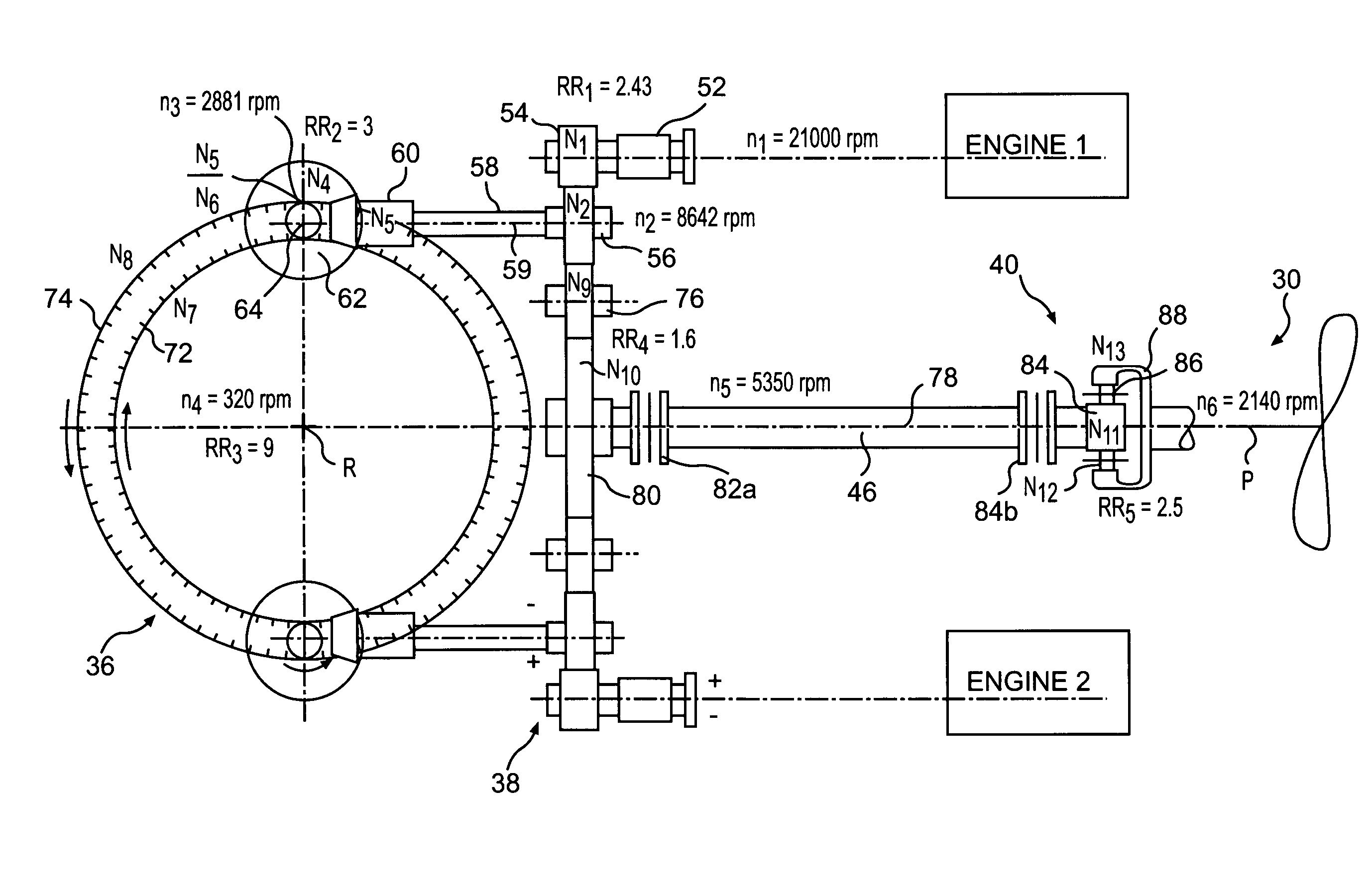
[0022]The translational thrust system 30 preferably includes a pusher propeller 32 having a propeller rotational axis P oriented substantially horizontal and parallel to the aircraft longitudinal axis...


PUM


Abstract

A gearbox of a high speed compound rotary-wing aircraft includes a main module, an input module and a translational thrust module. The input module receives power from the engines to drive a dual, contra-rotating, coaxial main rotor system and a translational thrust system which provides significant translational thrust generally parallel to an aircraft longitudinal axis. Each of a multiple of engine drives the input module such that power is distributed to the main module and the translational thrust module. The gearbox provides a lightweight solution, since each module need only transmit a required fraction of available engines power.

Description

BACKGROUND OF THE INVENTION[0001]The present invention relates to a split torque gearbox, and more particularly to a main gearbox for a rotary wing aircraft which directs significant power to a tail mounted pusher prop system.[0002]A gearbox system of a rotary wing aircraft transfers power from a turbine engine to the rotor system. A typical system may direct power from several turbine engines to a single rotor system which may include a multiple of blades. Since the rotational velocity of the rotor is significantly lower than the rotational velocity of the turbine engines, the turbine engine rotational velocity must be reduced by the gearbox system. In reducing the rotational velocity of the turbine engine output, torque is increased through a series of intermediate gear stages and shafts, before the final output drive is provided to the rotor.[0003]Conventional rotary-wing aircraft have a forward airspeed limited by a number of factors. Among these is the tendency of the retreatin...

Claims


Application Information

Patent Timeline
19 Aug 2008
Publication
US7413142B2
IPC
F16H35/18; B64D35/06
CPC
B64C27/10; B64C27/14; Y10T74/19144
Inventors
GMIRYA, YURIY