
Energy and media connection for a coating installation comprising several chambers

a technology of energy and media connection and coating installation, which is applied in the direction of chemical vapor deposition coating, multiple way valve, machine/engine, etc., can solve the problems of high the cathode, and achieve the maintenance of the coating chamber also simplified, the time expenditure for the reconfiguration of the coating installation is considerably reduced, and the effect of shortening the tim

Inactive Publication Date: 2008-08-19
APPLIED MATERIALS GMBH & CO KG
View PDF14 Cites 7 Cited by
  • Summary
  • Abstract
  • Description
  • Claims
  • Application Information

AI Technical Summary

Benefits of technology

Significantly reduces reconfiguration time and simplifies maintenance by enabling a single person to move the modules between chambers quickly, minimizing auxiliary resources required and allowing for efficient adaptation to different coating processes.

Problems solved by technology

This adaptation of a coating chamber to a new cathode entails very high expenditures.

Method used


Image

  • Energy and media connection for a coating installation comprising several chambers
  • Energy and media connection for a coating installation comprising several chambers
  • Energy and media connection for a coating installation comprising several chambers

Examples


Embodiment Construction

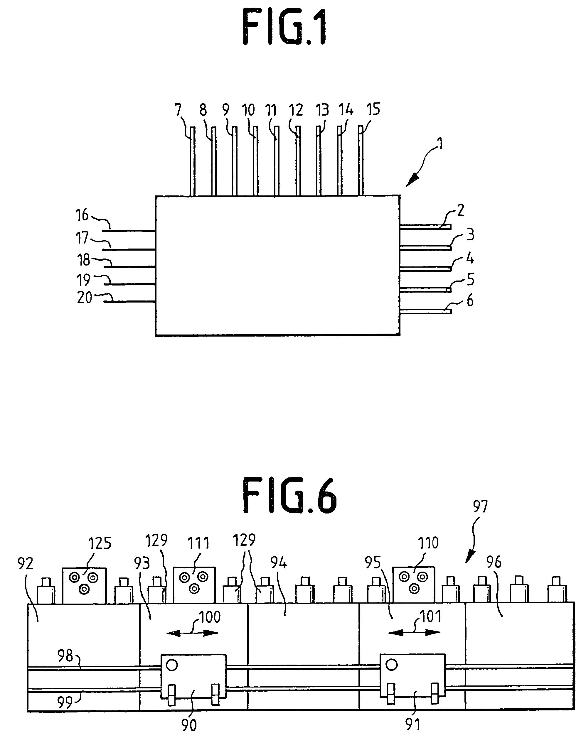
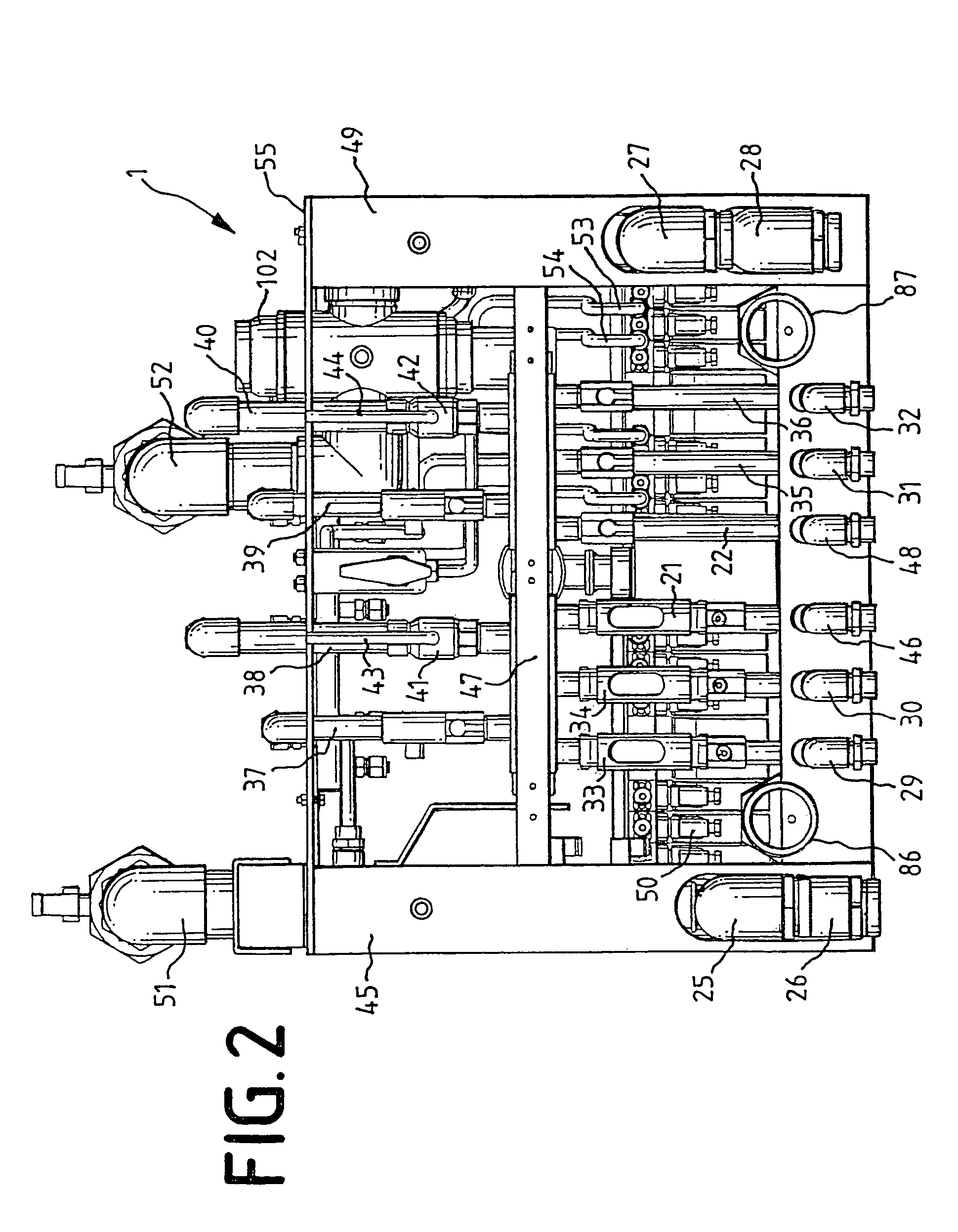
[0021]FIG. 1 shows a module 1 for energy and media connections in the form of a block. This module 1 comprises several cooling medium lines 2 to 6, for example a cooling medium line 2 for cooling a cathode with water and a cooling medium line 3 for cooling the environment of the cathode as well as a cooling medium line 4 for cooling the wall opposite the cathode. By 5 and 6 are denoted reserve cooling medium lines, which are required for cooling other structural parts in a coating, installation.

[0022]In addition to the cooling medium lines 2 to 6, the module 1 also comprises gas supply lines 7 to 15. With the gas supply line 7 for example argon is introduced into the process or coating chamber, while with the gas supply line 8 nitrogen is supplied. The gas supply line 9 serves analogously for supplying oxygen. If needed, further gases can be introduced into the process chamber with gas supply lines 10 to 15. They can also serve as purging lines or compressed air lines.

[0023]Lines 16...


PUM

PropertyMeasurementUnit
shapeaaaaaaaaaa
areasaaaaaaaaaa
poweraaaaaaaaaa

Abstract

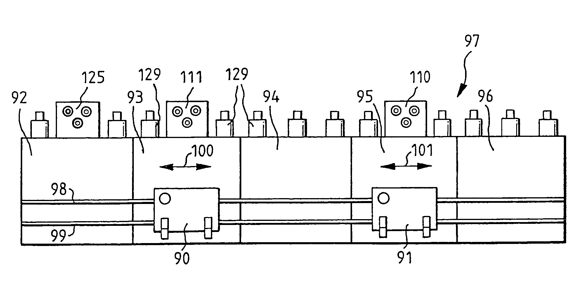
The invention relates to an energy and media connection module for coating installations. Said module serves for supplying with cooling water, compressed air, process gases, signal, control and cathode power. It can be moved from one coating chamber to another coating chamber along a coating line by a single person in a short time. Further, it is possible to separate the energy connection module from a coating chamber for maintenance or displacement purposes without mechanically demounting all connections.

Description

FIELD OF THE INVENTION[0001]This application claims priority from German Patent Application 10 2004 006 419.9 filed Feb. 9, 2004, which is hereby incorporated by reference in its entirety.[0002]The invention relates to an energy and media connection.BACKGROUND AND SUMMARY OF THE INVENTION[0003]Coating installations, for example for glass, often comprise a cathode and an anode, between which a voltage generating a plasma obtains. With the aid of this plasma certain substances are deposited on the glass, be that by sputtering or another method. During sputtering, the cathode is strongly heated since positively charged particles impinge out of the plasma onto a target connected with the cathode and knock atoms or molecules out of it, which subsequently become deposited on the glass.[0004]To keep the heating of the cathode within limits, it is cooled and specifically, as a rule, with a fluid medium, for example water. For this purpose special water supply lines are required. Apart from ...

Claims


Application Information

Patent Timeline
Patent Type & Authority Patents(United States)
IPC IPC(8): C23C14/35C23C16/00C03C21/00C23C14/34C23C14/56F04B27/02F16K11/02H01J37/32H01J37/34H01L51/40
CPCH01J37/32522H01J37/34H01J37/32577C03C21/00
Inventor HATTENDORF, GUIDORODLING, GERTRIST, GERHARD
Owner APPLIED MATERIALS GMBH & CO KG
Learn More