
Material separation device

Inactive Publication Date: 2008-08-19
DELTADOT
View PDF9 Cites 9 Cited by
  • Summary
  • Abstract
  • Description
  • Claims
  • Application Information

AI Technical Summary

Benefits of technology

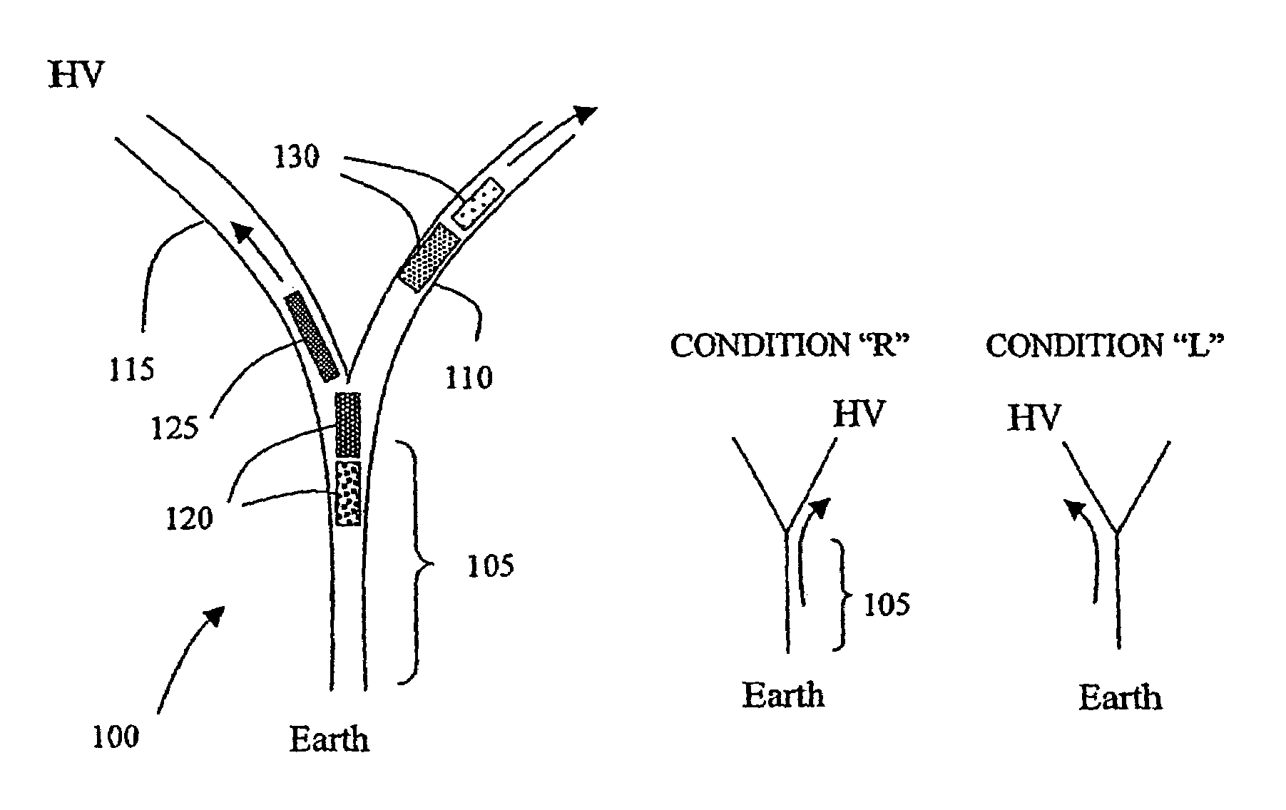
[0011]Embodiments of the present invention can be used to provide fast switching between collection channels for components with little cross-talk and thus precise collection of a component.
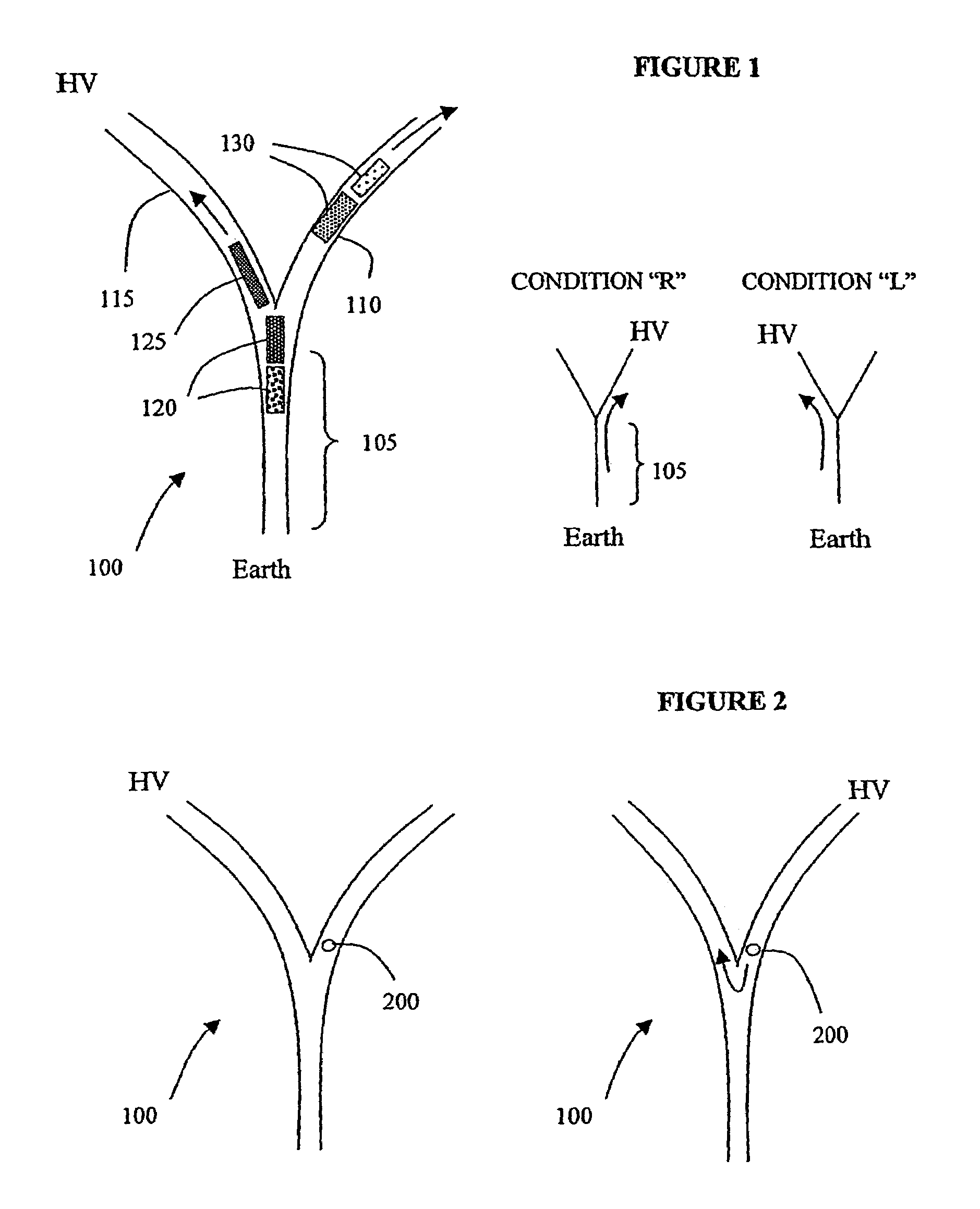
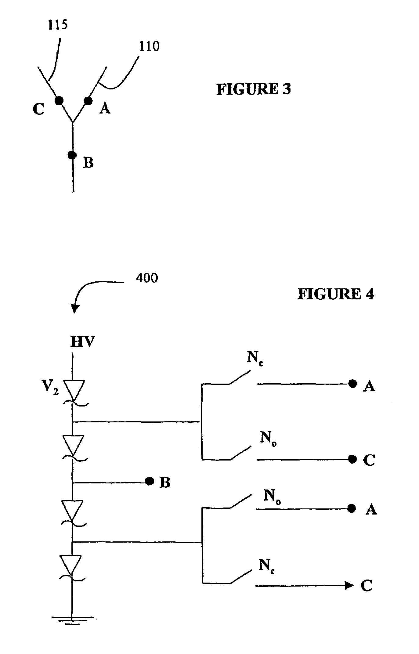
[0018]In a second arrangement, the separating device might comprise a voltage source for connection to all the subsidiary channels at the same time to produce a potential difference along the feed channel and each subsidiary channel, the voltage control means comprising means for short circuiting a point along the feed channel to a point along at least one of the subsidiary channels, in the region of the branch point for that subsidiary channel. This second arrangement is particularly advantageous because it means it is not necessary to switch a high voltage in order to change a subsidiary channel for collection of a component. This arises because the voltage source which is connected to produce a potential difference along the feed channel and at least one subsidiary channel is usually a high voltage source, designed to develop relatively quick differential migration of the components along the feed channel for collection into a subsidiary channel. By using the short circuiting arrangement described, only lower voltages need be switched to achieve the change in local conditions at a branch point which determine the direction taken by a component currently in the region of the branch point.

Problems solved by technology

A problem arises with this known arrangement when there is a need to change the potential difference at the branch point relatively rapidly, for instance to switch the next constituent molecular band into a different channel.
There is a risk that at least the tail end of the constituent molecular band which has just been switched into a side channel will start to migrate back to the branch point and may leave the side channel again.
These effects can lead to cross-contamination of the separated constituent molecular bands.

Method used


Image

  • Material separation device
  • Material separation device
  • Material separation device

Examples


Embodiment Construction

[0030]In electrophoresis, charged particles such as biomolecules move through a medium along a channel under the influence of an applied electric field. The channel can for instance be microfabricated on a chip, or might be a branched capillary tube. A voltage difference is applied between the ends of the channel. Charged particles inserted into the channel at one end (determined by the direction of the voltage difference and the effective charge of the particles) will move to the other end of the channel under the influence of the electric field. Particles having different characteristics move along the channel at different rates and thus mixed particles will separate into different groups as they move along the channel. It is useful to be able to collect one or more separated groups of particles and this can be accomplished by using a channel with multiple branches and by switching the flow of particles among the different branches in a timed fashion. One possible configuration of...


PUM

PropertyMeasurementUnit
Flow rateaaaaaaaaaa
Polarityaaaaaaaaaa
Electric potential / voltageaaaaaaaaaa

Abstract

A separating device for use in separating electrically charged components, e.g., by electrophoresis, comprises a channel branched at a branch point to provide a main feed channel (105) connected to at least two subsidiary channels (110, 115). In use, different components (120, 125, 130) show differential migration along the feed channel (105) so they can be separated into different subsidiary channels (110, 115) at the branch point. To support this separation, the separating device is provided with switchable voltage control means for controlling local voltages in a region of the branch point to provide potential differences of opposing polarity along the respective subsidiary channels (110, 115) such that a component to be separated (125) can be caused to migrate from the feed channel into a different subsidiary channel (115) from one or more other components.

Description

CROSS-REFERENCE TO RELATED APPLICATIONS[0001]This Application is a U.S. National filing under § 371 of International Application No. PCT / GB03 / 002926, with an international filing date of Jul. 8, 2003, now pending, claiming priority from Great Britain Application No. GB02 / 15779.0, with a filing date of Jul. 8, 2002, now pending, and herein incorporated by reference.[0002]1. Technical Field[0003]The present invention relates to a device and to a method for separating materials (e.g. biomolecules). It finds particular although not exclusive application in microchannel voltage switching, for instance for use in electrophoresis.[0004]2. Background of the Invention[0005]Electrophoresis is a technique known for use in the laboratory to separate charged entities such as molecules. For example, DNA fragments can be separated out in this way. If an electric current is applied to a sample carried in a microchannel, the sample can be caused to migrate along the microchannel. In doing so, differ...

Claims


Application Information

Patent Timeline
IPC IPC(8): G01N27/447B01L3/02B01D57/02B01L3/00B03C5/00B81B1/00G01N37/00
CPCB01D57/02B01L3/502738B01L3/502761G01N27/44791G01N27/44704G01N27/44713B01L2200/0647B01L2400/0415B01L2300/0864
Inventor HASSARD, JOHNMCKIGNEY, ED
Owner DELTADOT
Learn More