

Servo control system
a technology of servo control and control system, applied in the direction of program control, electric controller, instruments, etc., can solve problems such as defined inherent steady-state errors
- Summary
- Abstract
- Description
- Claims
- Application Information
AI Technical Summary
Benefits of technology
Problems solved by technology
Method used
Image

Examples
Embodiment Construction
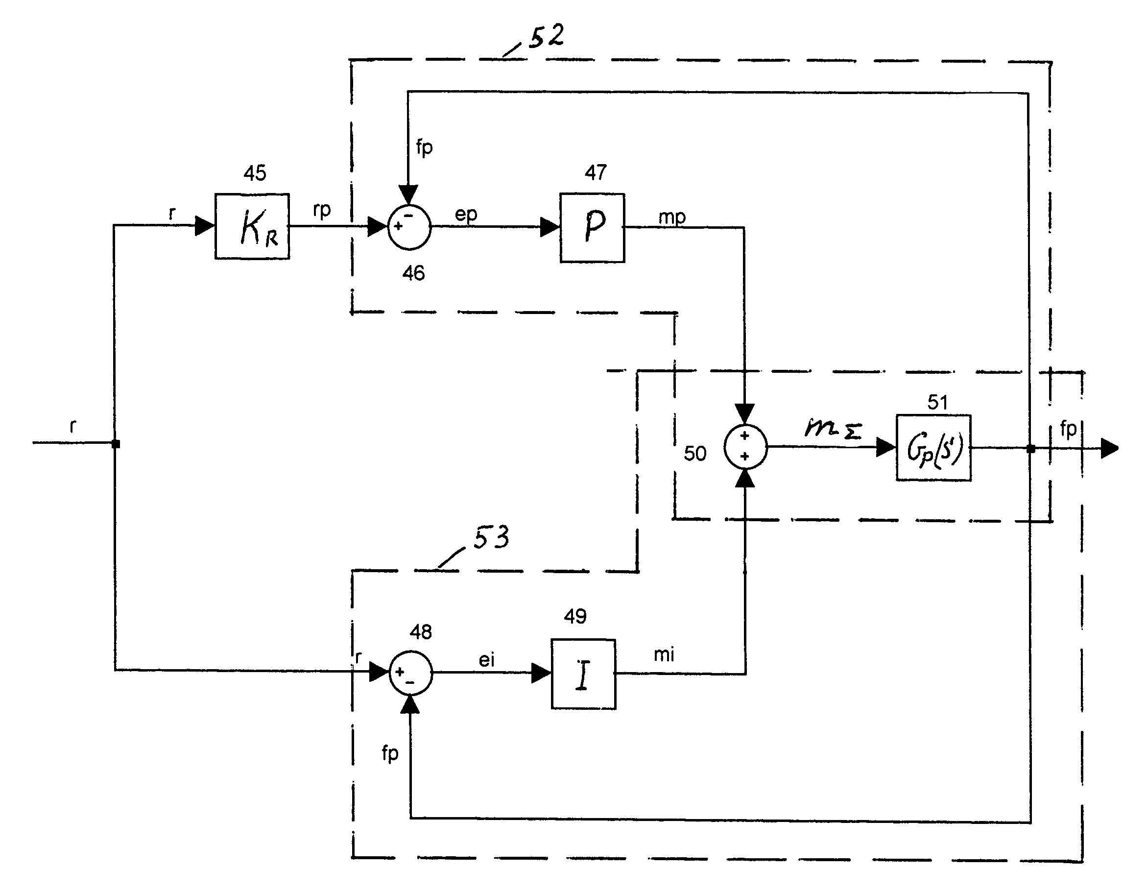
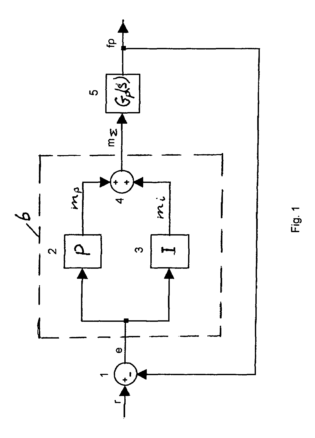
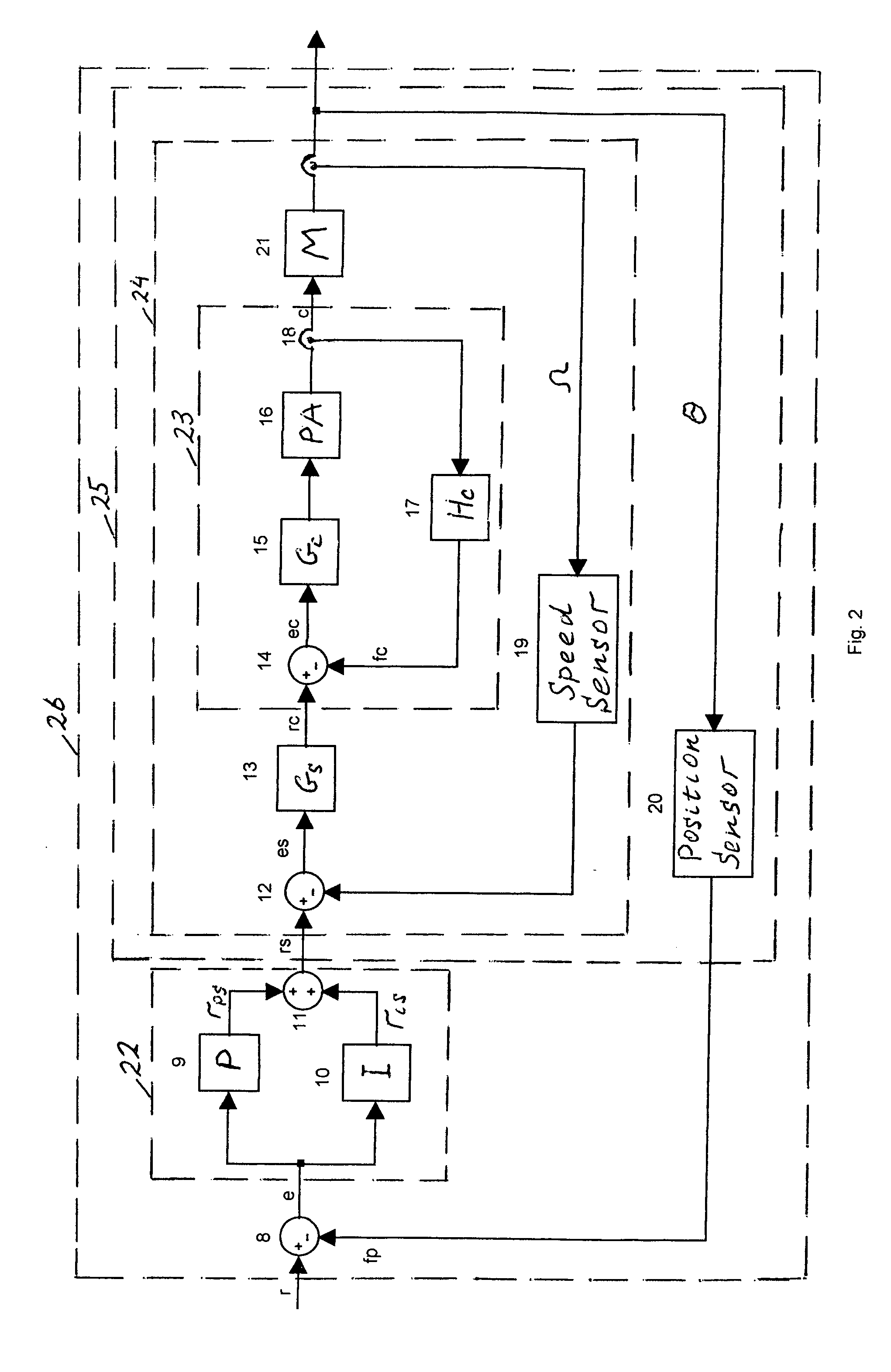
[0018]It is an objective of the present invention to provide a servo control system with a position PI controller achieving a decreased transient response time, that is better in performance to that which is achievable by conventional type ‘0’ servo control system.
[0019]Another objective of the present invention is to provide a position steady-state error equal to zero or close to zero as in conventional type ‘1’ servo control systems in order to enhance the speed of the system response and to provide precise motor positioning.
[0020]It is a further objective of this invention to reduce the noise of the system.
[0021]To achieve these objectives, an improved servo control system, according to the present invention, includes in one aspect two position close loops, where the position controller detects the position deviation between a position reference signal and a position feedback signal separately for the P part controller in order to produce a P part input speed reference signal, an...
PUM
 Abstract
Description
Claims
Application Information