Isulated concrete form having welded wire form tie

a technology of welded wire and concrete form, which is applied in the direction of machines/engines, manufacturing tools, liquid fuel engines, etc., can solve the problems of significant labor required to remove forms, insufficient insulation of walls, and common prior art techniques with significant drawbacks, and achieves simplified construction and increased structural strength.

Inactive Publication Date: 2008-08-26
AIRLITE PLASTICS
View PDF44 Cites 24 Cited by
  • Summary
  • Abstract
  • Description
  • Claims
  • Application Information

AI Technical Summary

Benefits of technology

[0027]A primary advantage of the present invention is that the wire ties provide increased structural strength between the opposing panels of the ICF.
[0028]Another advantage of the present invention is that construction is simplified, in that there is no defined “inside” or “outside” on forms, and forms may be connected in a horizontal orientation such that either end of any ICF may be joined to either end of any other ICF.
[0029]Other objects, advantages and novel features, and further scope of applicability of the present invention will be set forth in part in the detailed description to follow, taken in conjunction with the accompanying drawings, and in part will become apparent to those skilled in the art upon examination of the following, or may be learned by practice of the invention. The objects and advanta

Problems solved by technology

This common prior art technique has significant drawbacks.
The resulting wall is not insulated, and significant labor is required to remove the forms after the concrete cures or hardens.
However, all such forms can only be interconnected in a horizontal dimension in a specific direction, and the forms are not reversible.
However, all such forms have significant limitati

Method used


Image

  • Isulated concrete form having welded wire form tie
  • Isulated concrete form having welded wire form tie
  • Isulated concrete form having welded wire form tie

Examples


Embodiment Construction

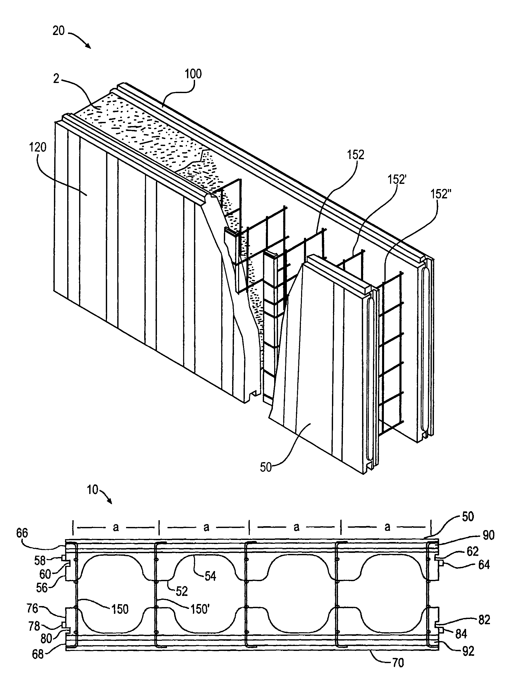
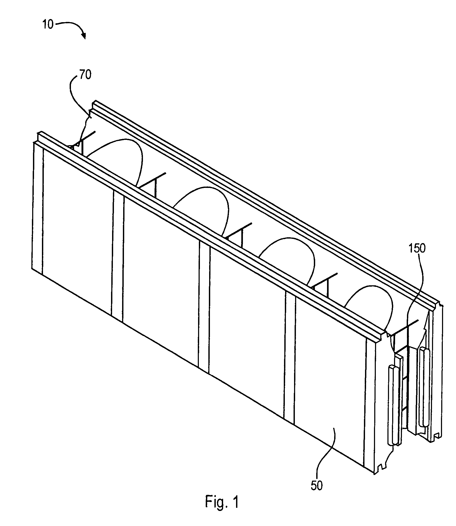
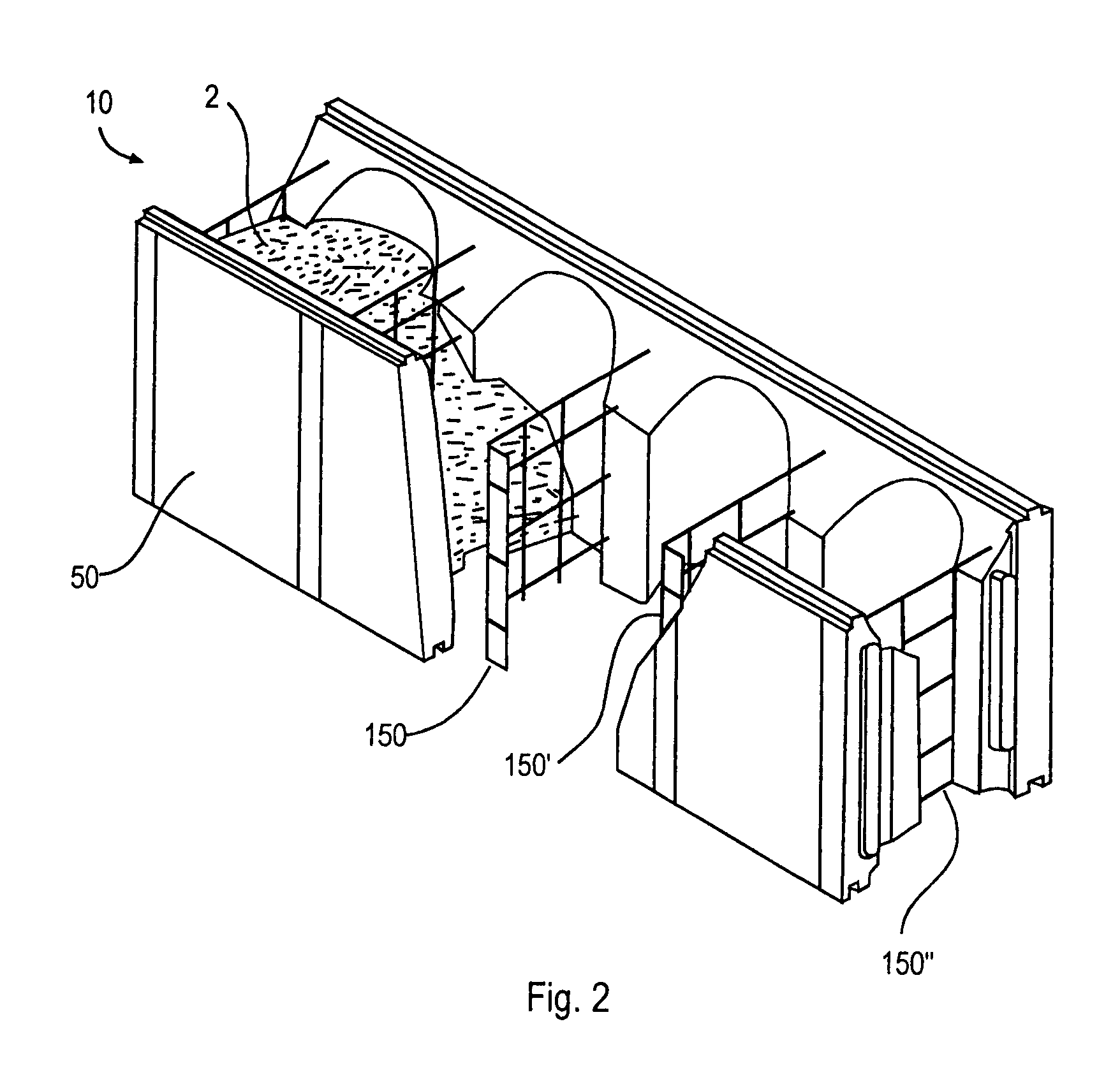
[0053]FIG. 1 depicts waffle grid form 10 of the invention, made of opposing panels 50 and 70 joined together by a plurality of metal ties 150. Panels 50 and 70 are preferably made of an insulating polymeric material, which is preferably a moldable polymeric material. In a preferred embodiment, panels 50 and 70 are made of an expanded polystyrene material, with a density of approximately 1.5 lbs. per cubic foot. Waffle grid form 10 may be provided in a variety of widths; in one embodiment, the form has an overall width of about 9.25 inches, with a maximum concrete core width of about 6 inches; in another embodiment, the form has an overall width of about 11 inches, with a maximum concrete core width of about 8 inches; and in yet another embodiment, the form has an overall width of about 14 inches, with a maximum concrete core width of about 10 inches. Waffle grid form 10 may be any convenient length suitable for use in construction; in one embodiment the form has a length of 48 inche...


PUM

PropertyMeasurementUnit
Angleaaaaaaaaaa
Angleaaaaaaaaaa
Polymericaaaaaaaaaa

Abstract

An insulating concrete form with two opposing panels, each panel having on each end thereof both a tongue and a groove for interconnecting with a similar form, the tongues and grooves positioned such that a similar form may be reversibly positioned and still interconnected, the opposing panels on each form joined by a plurality of metal wire ties with both horizontal and vertical members, preferably welded one to another, with each horizontal wire bent to form a right angle on each end with a metal attachment strip disposed within such right angle.

Description

CROSS-REFERENCE TO RELATED APPLICATIONS[0001]This application claims the benefit of the filing of U.S. Provisional Patent Application Ser. No. 60 / 408,859, entitled “Insulated Concrete Form and Welded Wire Form Tie”, filed on Sep. 5, 2002, and the specification thereof is incorporated herein by reference.BACKGROUND OF THE INVENTION[0002]1. Field of the Invention (Technical Field)[0003]The present invention relates to a horizontally reversible insulating concrete form with opposing panels connected by wire ties, preferably welded wire ties with a metal sheet attachment stud, used to make concrete structures.[0004]2. Description of Related Art[0005]Traditional concrete walls in building construction are generally made by setting up two parallel form walls and pouring concrete into the space between the forms. After the concrete hardens, the builder then removes the forms, leaving the cured concrete wall.[0006]This common prior art technique has significant drawbacks. The resulting wall...

Claims


Application Information

Patent Timeline
IPC IPC(8): E04B2/86E04B1/16B28B7/10B28B23/02F04C3/02
CPCE04B2/8617E04B2002/867
Inventor COOMBS, JERRY D.HORGAN, ANDREW M.WATSON, DAVID W.MURPHY, PATRICK C.
Owner AIRLITE PLASTICS
Why Eureka
Try Eureka