Swiveling work machine

a work machine and swivel technology, applied in the direction of tank vehicles, transportation and packaging, transportation items, etc., can solve the problems of not having the space provided for the disposal of the control valve unit, and the fuel tank is subject to undesirable heat influence, so as to effectively shield the influence of heat and minimize the influence of heat. , the effect of high strength

Active Publication Date: 2008-08-26
KUBOTA LTD
View PDF11 Cites 4 Cited by
  • Summary
  • Abstract
  • Description
  • Claims
  • Application Information

AI Technical Summary

Benefits of technology

[0008]In view of the above-described state of the art, a primary object of the present invention is to provide a swiveling work machine which allows easy maintenance of a control valve unit even when this control valve unit is disposed on the same right or left side on the swivel deck as the fuel tank and the battery and which can also restrict disadvantageous influence of heat from the work oil tank to the fuel tank.
[0014]With the above construction, the gap formed between the work oil tank and the fuel tank can effectively restrict adverse influence of heat from the work oil tank to the fuel tank.
[0018]With the above-described construction, the battery is supported to the swivel deck via the first plate and the pair of stays of the support frame and the control valve unit is supported to the swivel deck via the second plate and the pair of stays of the support frame. Therefore, these components, i.e. the battery and the control valve unit, are accommodated within the accommodating space while being supported to the swivel deck via the support frame. Moreover, the pair of stays are connected together at their vertical intermediate portions by means of the first plate and connected together also at their upper ends by means of the second plate, so that the support frame is constructed in the form of a grating having high strength. Further, downwardly of the battery, there is formed a space surrounded by the pair of stays and the first plate, so that the battery and other work machine accessories which require occasional replacement can be accommodated within this space.
[0019]According to one preferred embodiment of the present invention, a front portion of the second plate extends to a position upwardly of the fuel tank. With this construction, the battery and the fuel tank are covered by the second plate which mounts the control valve unit thereon. Hence, there is no possibility of splashing of oil during a maintenance operation of the control valve unit onto the battery or the fuel tank, so that a cleaning operation of these components, i.e. the work oil tank, the fuel tank, the battery and the control valve unit can be carried out easily. Moreover, the second plate can serve also to effectively shield the influence of heat from the control vale to the fuel tank.
[0020]According to one preferred embodiment of the present invention, at least one of a front lower portion of the work oil tank and a rear portion of the fuel tank extends into a portion of said gap on the inner side of the swivel deck than the battery. With this construction, the work oil tank and the fuel tank are placed in opposition to each other only at their portions extending into the gap. Hence, this construction can minimize the influence of heat from the work oil tank to the fuel tank. In addition, the work oil tank and / or the fuel tank can be formed larger advantageously, without enlarging the accommodating space. As a result, the gap can be utilized even more efficiently. Moreover, as the battery is disposed on the outer side of the swivel deck, this construction is advantageous also for facilitating e.g. the maintenance of this battery.

Problems solved by technology

However, in the case of the conventional backhoe disclosed in the above-cited document, the control valve unit is not disposed at the right side region on the swivel deck where the work oil tank, the fuel tank and the battery are disposed and no space allowing disposal of the control valve unit is provided, either.
Further, in the case of this conventional backhoe, the front face of the work oil tank is placed in opposition, over substantially entire area thereof, to the fuel tank, so that the fuel tank tends to be subjected to undesirable influence of heat from the work oil tank.

Method used


Image

  • Swiveling work machine
  • Swiveling work machine
  • Swiveling work machine

Examples


Embodiment Construction

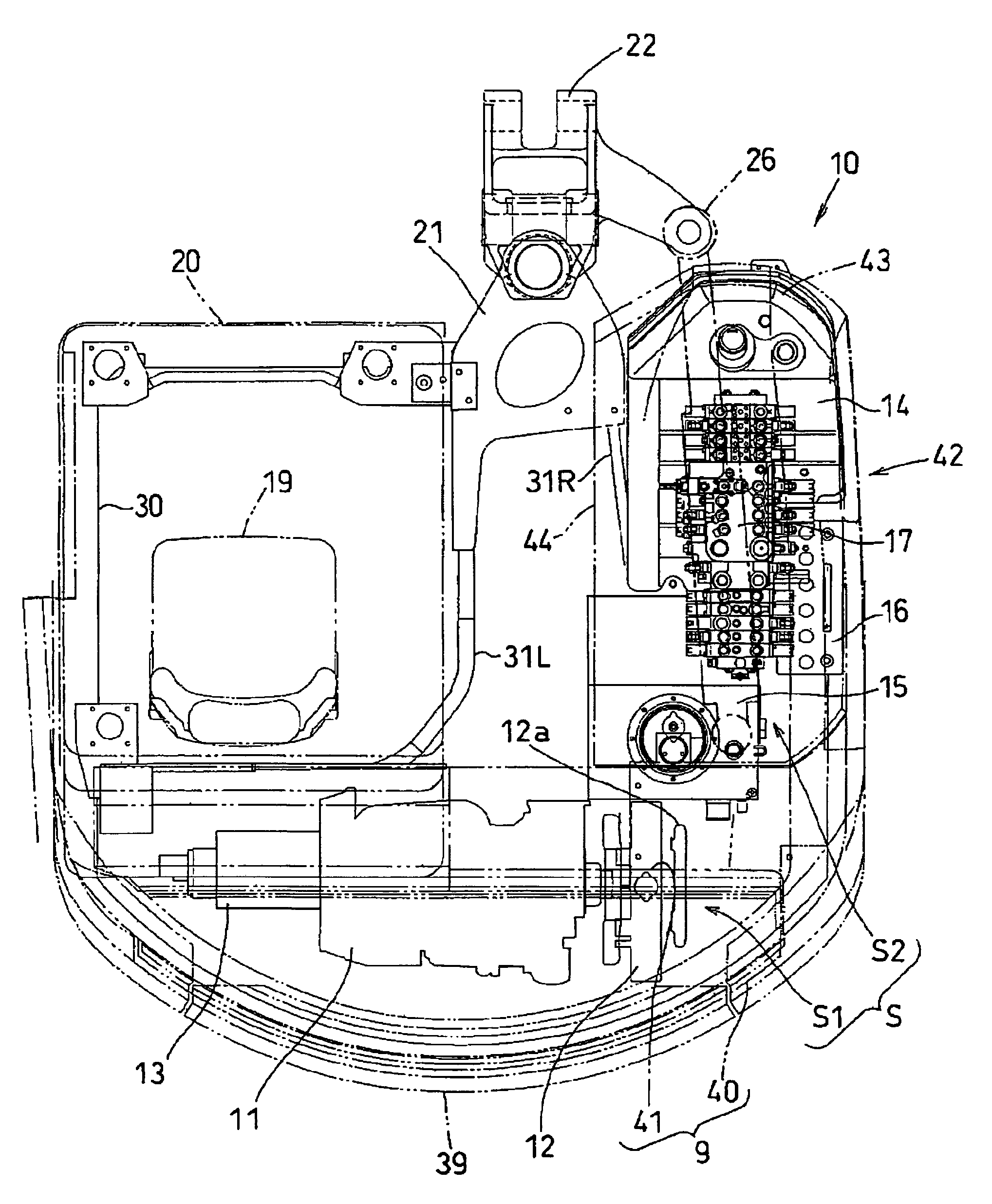
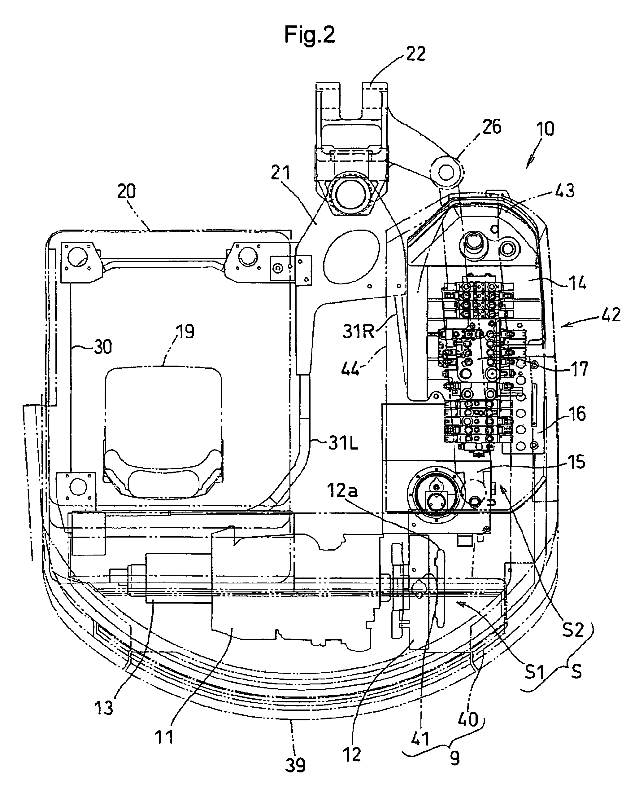
[0034]Next, with reference to the accompanying drawings, preferred embodiments of the present invention will be described in details, with taking a backhoe as an example of a swiveling work machine.

[0035]In the following discussion, a direction along which the backhoe travels forward or rearward without steering will be referred to as a fore / aft direction, a direction orthogonal to this fore / aft direction will be referred to as right / left direction, and a direction orthogonal to both the fore / aft direction and the right / left direction will be referred to as a vertical direction, respectively.

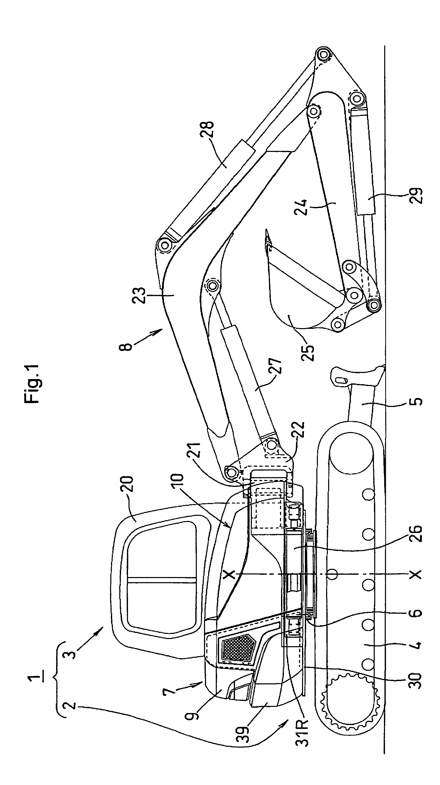
[0036]As shown in FIG. 1, the backhoe 1 relating to the present invention is comprised mainly of a traveling unit 2 disposed at a lower section of the backhoe and a swivel body 3 disposed at an upper section of the same.

[0037]The traveling unit 2 comprises a crawler type traveling unit including a pair of right and left traveling devices 4 each having an endless crawler belt made of rubber or me...


PUM


Abstract

A swiveling work machine includes a swivel deck mounted to be pivotable about a vertical axis and a side cover for covering one lateral side on the swivel deck, an accommodating space capable of accommodating a work machine accessory being provided inside the lateral cover. The accommodating space accommodates, as the implement accessory, a work oil tank, a fuel tank and a control valve unit. The work oil tank is disposed at a fore-and-aft intermediate portion on one lateral side on the swivel deck. The fuel tank is disposed forwardly of the work oil tank with forming a gap relative thereto. The control valve unit is disposed upwardly of the fuel tank and longitudinally along the fore / aft direction.

Description

BACKGROUND OF THE INVENTION[0001]1. Field of the Invention[0002]The present invention relates to a swiveling work machine such as a backhoe.[0003]2. Description of the Related Art[0004]Conventionally, in a swiveling work machine such as a backhoe, a swivel deck is mounted on a self-propelling machine body to be pivotable about a vertical axis. The swivel deck mounts, at a rear region thereof, such components as an engine, a radiator, a hydraulic pump, etc., which are all covered with a hood. The swivel deck includes also, at one of right and left regions thereof, an accommodating space for disposing work machine accessories such as a fuel tank, a work oil tank, a battery, a control valve unit, etc. and this accommodating space is covered with a side cover which extends from a front portion of the hood toward a front region of the swivel deck. The swivel deck further mounts, at the other of the right and left regions thereof, a driver's seat and between this driver's seat and the acc...

Claims


Application Information

Patent Timeline
Patent Type & Authority Patents(United States)
IPC IPC(8): B60P3/22
CPCE02F3/325E02F9/0875E02F9/2275E02F9/121E02F9/2271E02F9/0883
Inventor SATO, FUMIKISHIMOIE, SHIZUOKATO, YOSHIHIROMATSUMOTO, TAKANORIKOGA, KENZO
Owner KUBOTA LTD
Why Eureka
Try Eureka