
Methods of using a laser to spall and drill holes in rocks

a laser and rock formation technology, applied in the direction of directional drilling, manufacturing tools, pedestrian/occupant safety arrangements, etc., can solve the problems of increasing the drilling time and cost of well drilling, and saving well drilling time and cost. energy-saving

Active Publication Date: 2008-08-26
UCHICAGO ARGONNE LLC
View PDF4 Cites 60 Cited by
  • Summary
  • Abstract
  • Description
  • Claims
  • Application Information

AI Technical Summary

Benefits of technology

This method significantly reduces drilling costs and time by achieving 8-100 times faster rock removal compared to conventional techniques, with low power requirements and efficient debris removal through laser spallation, allowing for deeper and larger holes to be drilled with reduced mechanical stress and debris handling.

Problems solved by technology

Drill bits are often worn out or broken down during a deep well drilling.
All of these dramatically increase the well drilling time, and therefore the well drilling costs.
This saves well drilling time and costs.
This results in local thermal stresses in the rock subsurface.
The explosion of the vaporized liquid creates significant mechanical stresses in the rock.

Method used


Image

  • Methods of using a laser to spall and drill holes in rocks
  • Methods of using a laser to spall and drill holes in rocks
  • Methods of using a laser to spall and drill holes in rocks

Examples


Embodiment Construction

[0016]In accordance with features of the invention, a rock destruction process utilizes a combination of laser-induced thermal stress and laser induced superheated steam explosions just below the surface of the laser / rock interaction to spall or fracture the rock into small fragments that can then be easily removed from the rock formation. The method of the invention uses high power laser beams of kilowatt level to replace conventional mechanical drilling bits to rapidly drill large diameter and deep holes in rocks. It has been shown that short illumination of a single laser beam of irradiance about 1000 to 5000 W / cm2 can thermally spall rock and create a hole as large as the beam spot size and as deep as the hole diameter.

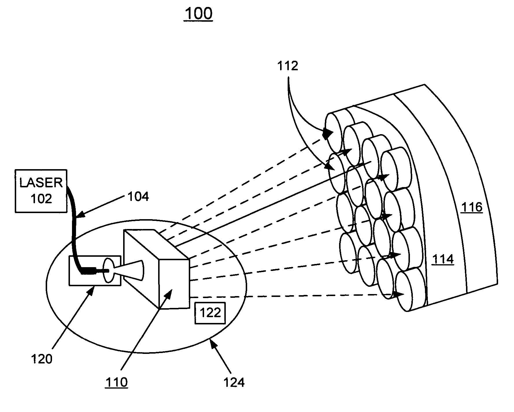
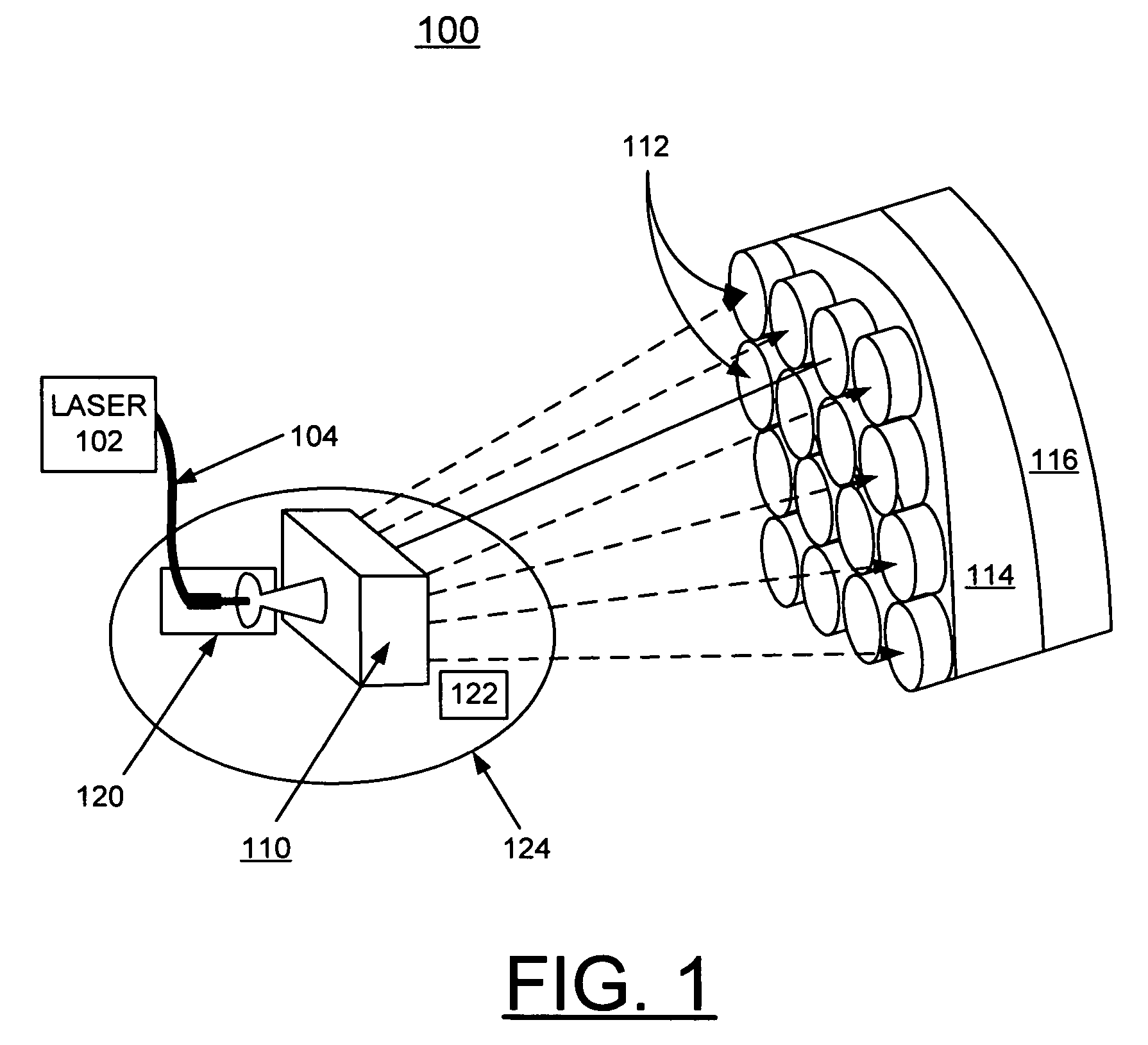
[0017]Having reference now to the drawings, in FIG. 1 there is shown apparatus generally designated by the reference character 100 for implementing methods of the invention in accordance with a preferred embodiment of the invention. Apparatus 100 includes a high p...


PUM

PropertyMeasurementUnit
hole diameteraaaaaaaaaa
diameteraaaaaaaaaa
irradianceaaaaaaaaaa

Abstract

Apparatus and methods of using lasers are provided for spalling and drilling holes into rocks. A rock removal process is provided that utilizes a combination of laser-induced thermal stress and laser induced superheated steam explosions just below the surface of the laser / rock interaction to spall the rock into small fragments that can then be easily removed by a purging flow. Single laser beams of given irradiance spall rock and create holes having diameter and depth approximately equal to the beam spot size. A group of the single laser beams are steered in a controllable manner by an electro-optic laser beam switch to locations on the surface of the rock, creating multiple overlapping spalled holes thereby removing a layer of rock of a desired diameter. Drilling of a deep hole is achieved by spalling consecutive layers with an intermittent feed motion of the laser head perpendicular to the rock surface.

Description

[0001]This application claims the benefit of U.S. Provisional Application No. 60 / 672,769, filed on Apr. 19, 2005.CONTRACTUAL ORIGIN OF THE INVENTION[0002]The United States Government has rights in this invention pursuant to Contract No. W-31-109-ENG-38 between the United States Government and Argonne National Laboratory.FIELD OF THE INVENTION[0003]The present invention relates to improved methods and apparatus for spalling and drilling holes into rock formations. More specifically this invention relates the use of lasers for spalling and drilling holes into rock formations.DESCRIPTION OF THE RELATED ART[0004]A conventional rotary drilling method for drilling gas and oil wells is the use of a drill bit on the end of a long length of drill pipe also called a drill string that is rotated by mechanical apparatus from the surface. The drill bit that actually cuts up the rock comes in many shapes and materials, such as tungsten carbide, steel, diamond, that are specialized for various dri...

Claims


Application Information

Patent Timeline
Patent Type & Authority Patents(United States)
IPC IPC(8): E21B7/14E21B7/15E21C35/24E21C37/16
CPCB23K26/0604B23K26/0676B23K26/4075B28D1/221E21B7/15B23K26/381B23K26/40B23K26/382B23K2103/50
Inventor REED, CLAUDE B.XU, ZHIYUEPARKER, RICHARD A.GRAVES, RAMONA M.STONE, THOMAS W.
Owner UCHICAGO ARGONNE LLC
Learn More