
Orthodontic appliance with embedded wire for moving teeth and method

a technology of orthodontic appliances and wires, applied in dental surgery, dental tools, medical science, etc., can solve the problems of expensive and difficult manufacturing of devices, inefficient and slow force teaching of patients' teeth, and only a limited ability of apparatuses to move teeth, etc., to achieve pain free and rapid movement of patients' teeth, and easy manufacturing.

Inactive Publication Date: 2008-08-26
CRONAUER EDWARD A
View PDF29 Cites 33 Cited by
  • Summary
  • Abstract
  • Description
  • Claims
  • Application Information

AI Technical Summary

Benefits of technology

The appliance provides more forceful and less obtrusive movement of teeth, allowing for rapid correction of tooth alignment and bite orientation, while being easy to manufacture and cosmetically invisible, with the ability to expose the chewing surface of front teeth.

Problems solved by technology

While these brackets are unattractive, they have shown that a wire can be used to rapidly move teeth.
However, these apparati have only a limited ability to move teeth.
However, Chishti only teaches the inefficient and slow use of force on the patient's teeth that is intrinsic to the resiliency in the plastic that forms the appliance.
Prior art inventions also include devices that are costly and difficult to manufacture.
Permanently attached braces are unsightly, inconvenient when eating or speaking and may cause discoloration or even pain to the patient.
The speed by which the prior art plastic devices move teeth is limited by the rigidity of the plastic used.
Not even modern plastics can provide sufficient force to quickly reorient the alignment of the teeth or the bite of a patient.

Method used


Image

  • Orthodontic appliance with embedded wire for moving teeth and method
  • Orthodontic appliance with embedded wire for moving teeth and method
  • Orthodontic appliance with embedded wire for moving teeth and method

Examples


Embodiment Construction

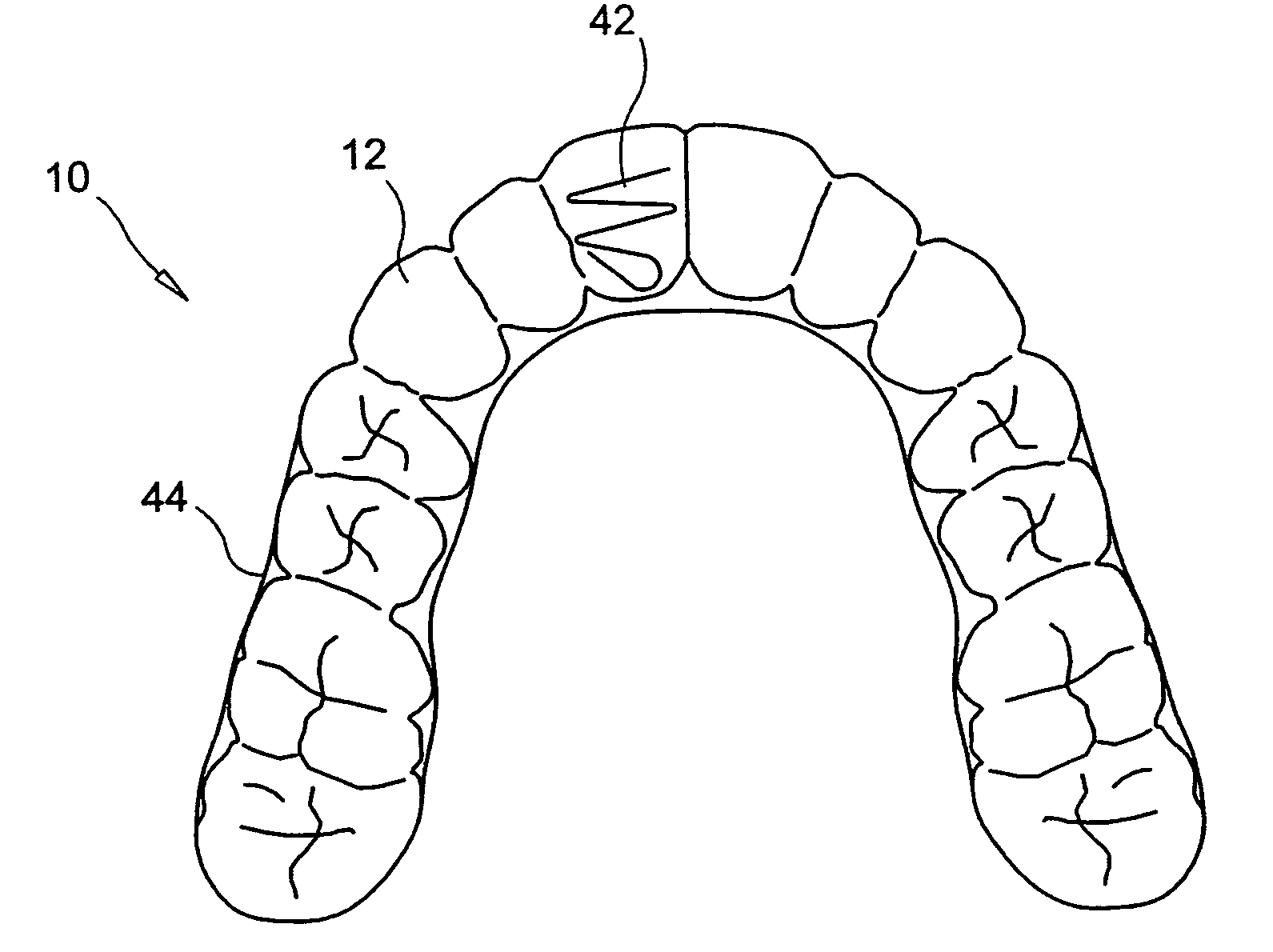
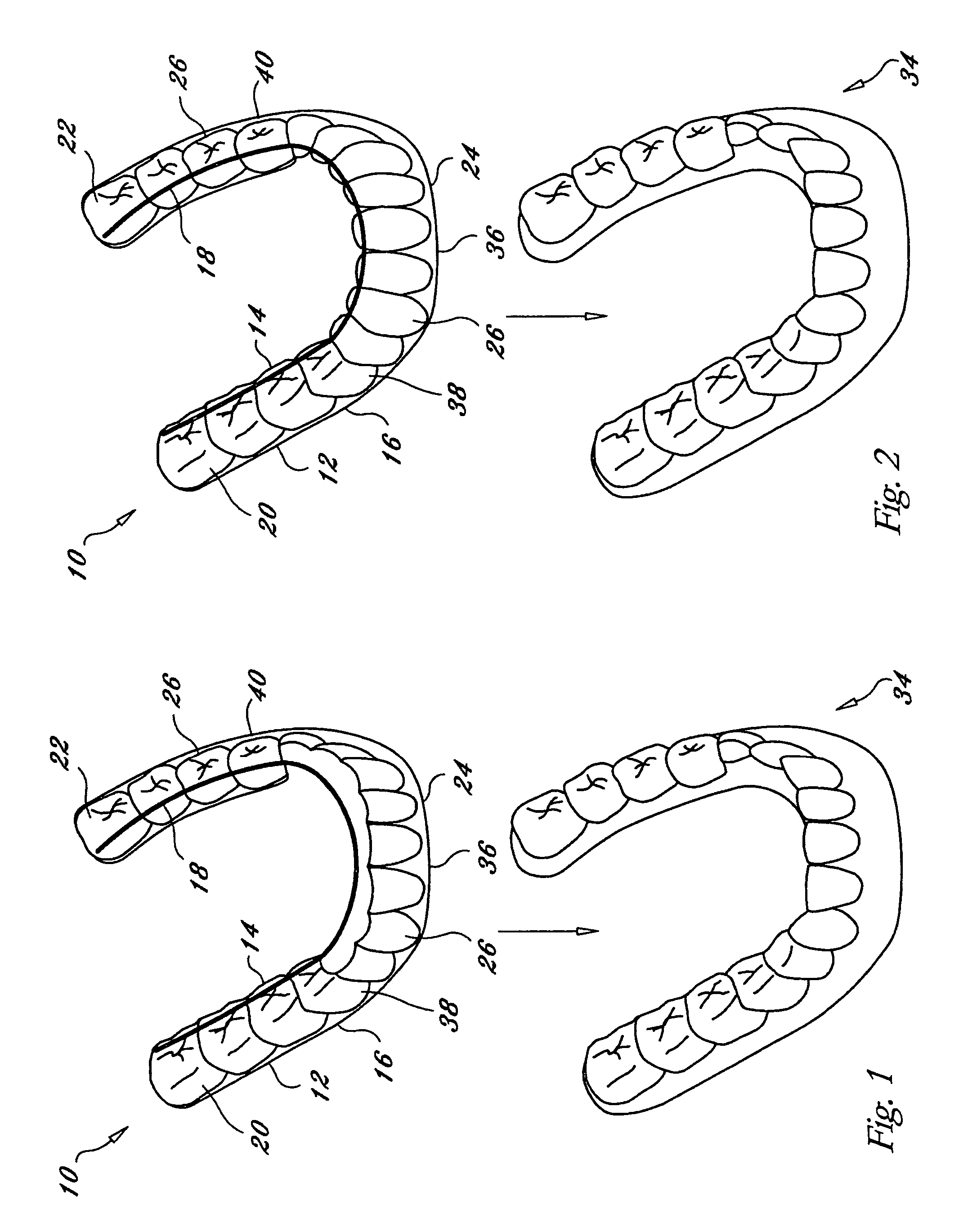
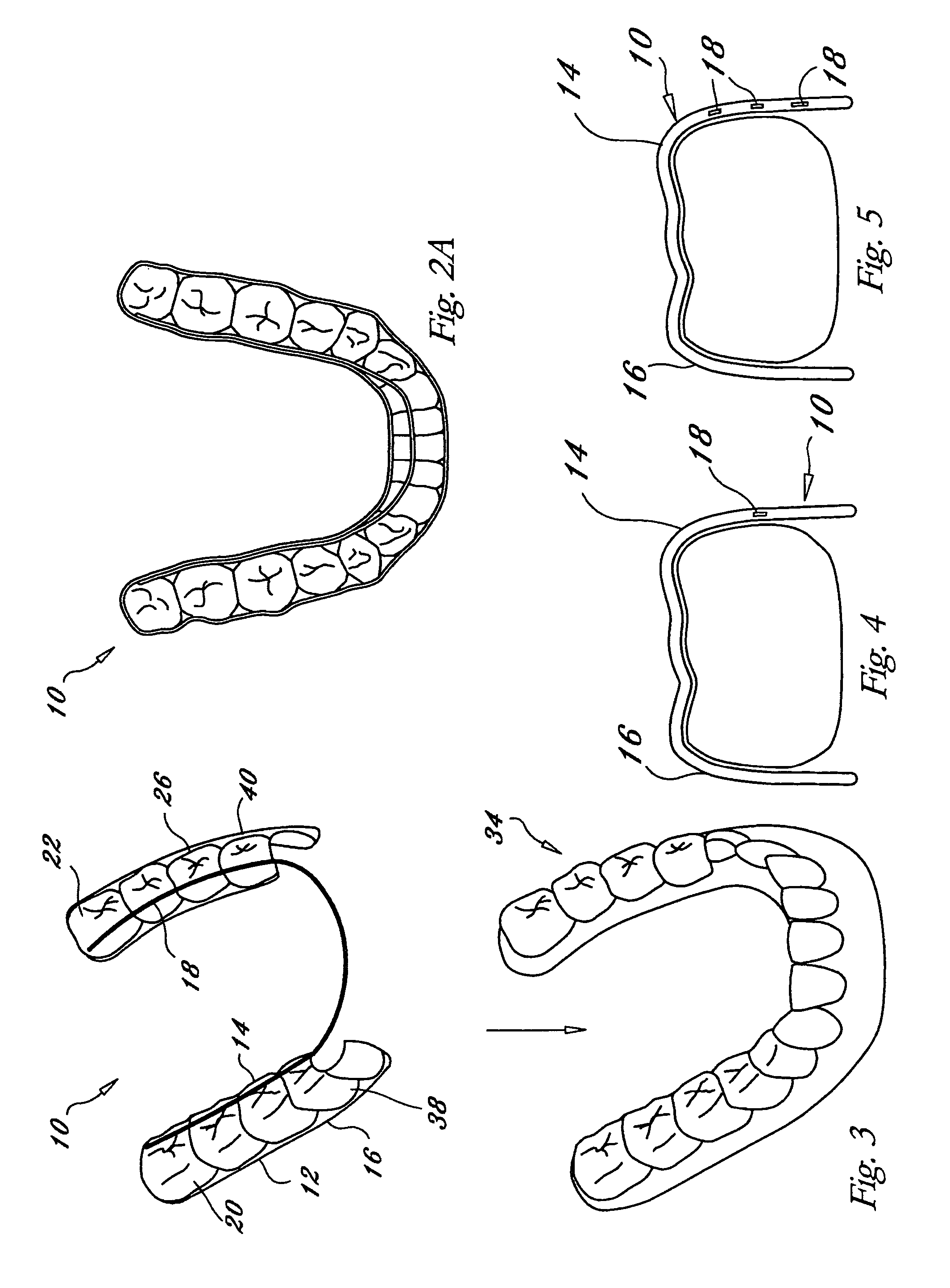
[0027]Referring now to the drawings and in particular, FIG. 1, the generally horseshoe shaped clear flexible resilient plastic orthodontic appliance for a patient is shown generally at 10. A plastic portion 12 has a lingual side 14 and a labial side 16. Both the lingual side 14 and the labial side 16 have concave contours 26. These contours 26 snugly contact the patient's teeth 34. The contours 26, especially those over the molars, allow the appliance 10 to remain fixed in place over the patient's teeth 34. The contours 26, especially those on the front 36 of the appliance 10, serve the function of guiding the force of the appliance 10 to move the patient's teeth 34 into an advantageous position. On the lingual side 14 of the appliance 10 are one or more flexible wires 18 at least partially embedded within the plastic portion 12. Preferably, the wires 18 are made of a nickel-titanium alloy or stainless steel, although other similar materials which would provide force on the patient'...


PUM


Abstract

A generally horseshoe shaped clear flexible resilient plastic wire-imbedded orthodontic appliance is made with a plastic portion with contours on the lingual side and on the labial side, wherein the contours snugly cover the patient's teeth so that the appliance remains in place. One or more flexible wires are imbedded within the lingual side of the plastic portion from the left molar area to the right molar area of the plastic portion, whereby the wires apply force on the lingual side of the patient's bite. The appliance is formed by obtaining a plaster cast of the patient's teeth and gums, removing plaster teeth from the plaster cast of the gums, reattaching the plaster teeth to the plaster cast of the gums to form a cast of proper bite alignment, attaching one or more wires to the labial surface of the aligned plaster teeth so the wires become imbedded within thermosetting plastic placed over the cast, putting the cast in a thermosetting plastic molding machine, inserting thermosetting plastic in the machine, and heating the thermosetting plastic around the cast of the proper bite alignment, so the wires are imbedded within the formed appliance after the thermosetting plastic cools. A series of appliances may be used to shift a patient's bite to proper bite orientation.

Description

[0001]This application is a Divisional Application of application Ser. No. 10 / 160,943 filed May 31, 2002, now U.S. Pat. No. 7,104,790 by Edward A. Cronauer, entitled ORTHODONTIC APPLIANCE WITH EMBEDDED WIRE FOR MOVING TEETH AND METHOD, the entirety of all of which is incorporated herein by reference.BACKGROUND OF THE INVENTION[0002]1. Field of the Invention[0003]Orthodontics is a specialty of dentistry dealing with the correction of a patient's bite and alignment of a patient's teeth. Currently, orthodontic appliances apply forces to the teeth of the patient. These forces physically shift the patient's teeth with precise and complex movements, to conform the teeth to a model created by the orthodontist or a laboratory specifically suited to the purpose.[0004]2. Description of Related Art[0005]Active treatment of the bite historically involved cementing brackets onto the teeth with one or more arch wires attached. While these brackets are unattractive, they have shown that a wire can...

Claims


Application Information

Patent Timeline
Patent Type & Authority Patents(United States)
IPC IPC(8): A61C3/00A61C7/08
CPCA61C7/08
Inventor CRONAUER, EDWARD A.
Owner CRONAUER EDWARD A
Learn More