Method for high speed machining and coated cutting tool

a cutting tool and high-speed technology, applied in the field of high-speed machining of metallic work pieces and a coated cemented carbide cutting insert, can solve the problem of high cost of ceramic tools, and achieve the effect of high-speed operations

Inactive Publication Date: 2008-08-26
SANDVIK INTELLECTUAL PROPERTY AB
View PDF15 Cites 22 Cited by
  • Summary
  • Abstract
  • Description
  • Claims
  • Application Information

AI Technical Summary

Benefits of technology

[0011]It is therefore an object of the present invention to provide cemented carbide cutting tools with the performance as ceramic cutting tools in high speed operations.
[0012]It has now been surprisingly found that coated cutting insert consisting of a substrate with high hardness and an unconventional thick coating can be used in high speed machining with essentially the same or better performance as ceramic cutting tool inserts.

Problems solved by technology

Ceramics are often used in applications requiring high productivity such as the machining of brake discs and other components in the car industry because cemented carbide can not withstand the high temperature generated during the high speed operations required to obtain the desired high productivity.
However, ceramic tools are expensive because of the high manufacturing cost.

Method used


Image

  • Method for high speed machining and coated cutting tool
  • Method for high speed machining and coated cutting tool

Examples


example 1

[0047]Cemented carbide substrates A-D with compositions according to table 1 were produced in the conventional way from powders, which were milled, pressed and sintered with or without grounding to insert shapes, ISO standard CNMA120416 T02020 and CNMA120416-KR. Furthermore the inserts were subjected to mechanical edge rounding.

[0048]After that the inserts were cleaned and coated using processes known in the art. Coating compositions and thicknesses appear from Table 2.

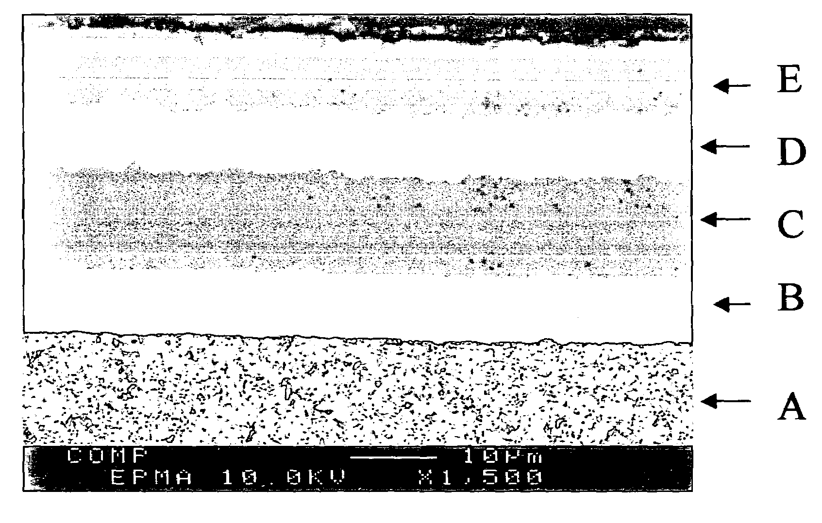
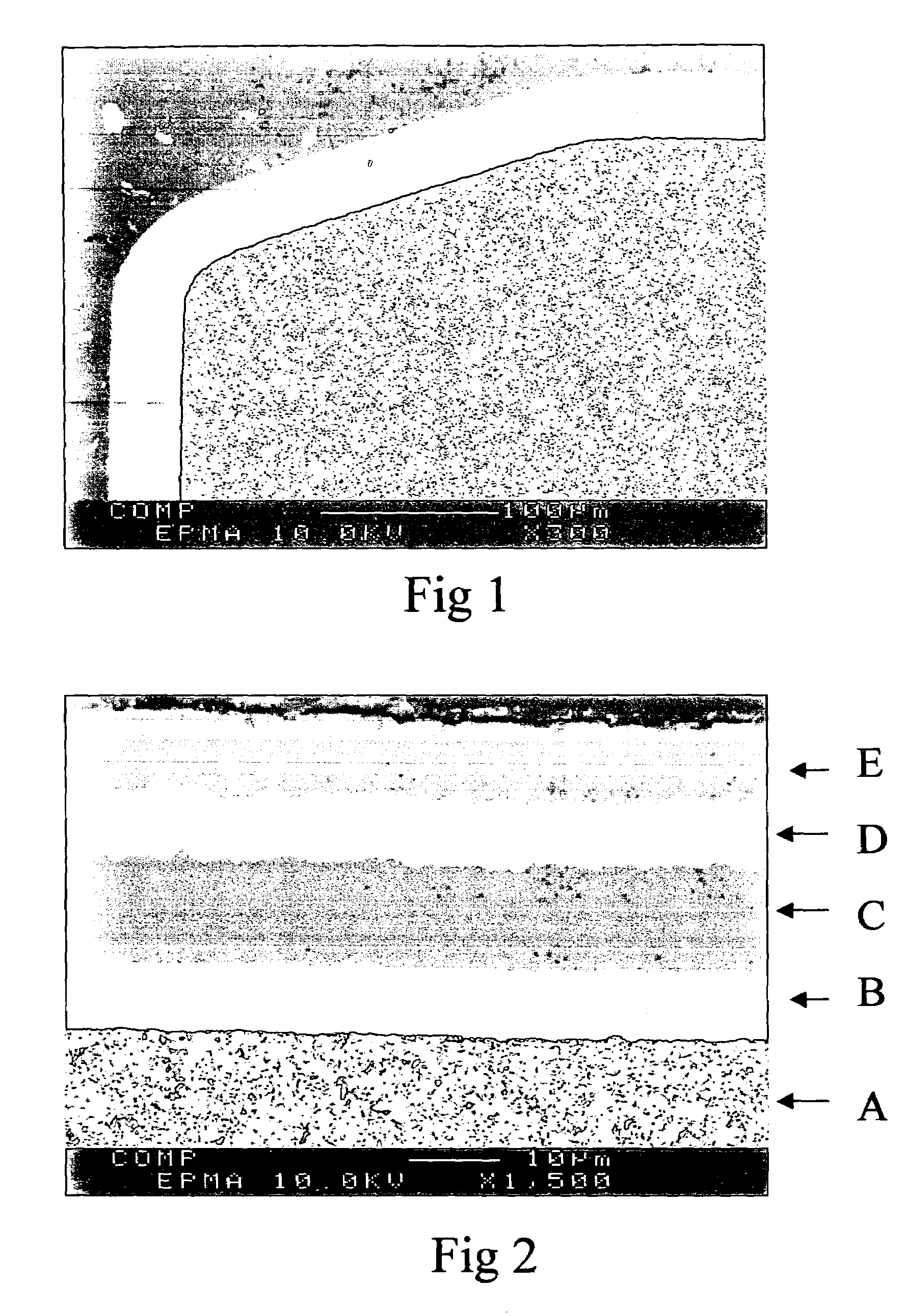
[0049]Two major types of layers Ti(C,N) and α-Al2O3 were deposited. Ti(C,N) was deposited so that a columnar grain structure of the layer was obtained. This was done by using the known MT-CVD process (MT-medium temperature, CVD-chemical vapor deposition) where besides other gases acetonitrile, CH3CN, was used as nitrogen and carbon source.

[0050]In the start of the coating process, at the transition zone between Ti(C,N) and Al2O3 layers and at the end of the coating process conventional processes were also used. These ...

example 2

[0054]Inserts of style CNMA120416 T02020 with an edge radius of 30 um (as measured on the uncoated insert) with substrates A, B and C with coating 1 or 2 or 6 designated A / 1, B / 2, B / 6 and C / 2, respectively and B / 4 and D / 5 were subjected to a high-speed cutting test in brake discs of a grey cast iron. The discs had a diameter of 139 mm, comprising small plane surfaces oriented at different angles towards the body axis. The flank wear width of the cutting edge after 150 discs was measured. As references were inserts B / 4 and commercially available Si3N4 ceramic insert with the same geometry used.

Machining Data

[0055]

Work piece:SS0120, grey cast iron.Type of operation:continuous internal turning operation.Cutting speed:varying from 500 to 1000 m / min, mostly over900 m / minDepth of cut:2-4 mm.Feed:0.5 mm / rev.Coolant:dry operation.Cutting time:per piece total up to 10 sec, comprising single cutsof various time lengths.RESULTS:InsertFlank wear, mmA / 1 invention0.17B / 2 invention0.18C / 2 inventio...

example 3

[0056]Example 2 was repeated with inserts A / 1, D / 1, A / 2, B / 2, A / 3, B / 6, B / 4 and C / 5 with brake discs of diameter 177 mm. The number of machined discs until the inserts were worn out was determined.

Cutting Data

[0057]

Work piece:SS0120, grey cast iron.Type of operation:continuous internal turning operation.Cutting speed:varying from 600 to 1200 m / min, mostly over1000 m / min)Depth of cut:2-4 mm.Feed:0.5 mm / rev.Coolant:dry operation.Cutting time:per piece total up to 10 sec, comprising single cutsof various time lengths.RESULTS:InsertNumber of discsA / 1 invention233D / 1 invention177A / 2 invention203B / 2 invention191A / 3 invention240B / 6 invention201B / 4 prior art80C / 5 prior art55Si3N4 ceramic / Reference217


PUM

PropertyMeasurementUnit
total thicknessaaaaaaaaaa
thicknessaaaaaaaaaa
thicknessaaaaaaaaaa

Abstract

The present invention relates to a method of machining a metal work piece with a coated cutting tool insert having a cemented carbide body and a coating deposited as monolayer(s) or as multiple and / or alternating layers. The coating has a total thickness of from about 25 to about 75 μm and the machining is performed at a cutting speed of greater than about 600 m / min, preferably from about 800 to about 1500 m / min. The invention also relates to a coated cutting tool useful for such machining operation.

Description

BACKGROUND OF THE INVENTION[0001]The present invention relates to a method for high speed machining of metallic work pieces and a coated cemented carbide cutting inserts particularly useful for that application.[0002]Cemented carbide cutting tools coated with various types of hard layers have been commercially available for years. Such tool coatings are generally built up by one Ti(C,N) hard layer and one Al2O3 hard layer where the Ti(C,N) is the innermost layer adjacent to the cemented carbide. The thickness of the individual layers is carefully chosen to suit different cutting applications and work-piece materials e g cast iron and stainless steel. More particularly, a coating generally comprises:[0003]a Ti-compound layer, as an inner layer, formed by CVD or MT-CVD with an average thickness of 2 to 10 μm made of one major Ti(C,N) layer or a plurality of two or more layers of TiC, TiN, Ti(C,N), Ti(C,O) and Ti(C,N,O)[0004]an Al2O3-layer, as an outer layer formed by CVD which has an ...

Claims


Application Information

Patent Timeline
Patent Type & Authority Patents(United States)
IPC IPC(8): B32B9/00B23B27/14C22CC23C30/00
CPCB23B27/148C23C30/005B23B2222/14B23B2224/04B23B2224/32B23B2224/36Y10T82/10B23B2228/105Y10T428/265Y10T428/24975B23B2228/04Y10T428/31678B23P17/00B23B1/00B23P17/02B23C1/00C23C16/30C23C16/403
Inventor WESTERGREN, KENNETHMIKUS, MARIANANG.KESSON, LEIF
Owner SANDVIK INTELLECTUAL PROPERTY AB
Why Eureka
Try Eureka