Monopulse radar estimation of target altitude at low angles of elevation

a radar and target technology, applied in the field of improved altitude estimates of targets, can solve the problems of large errors at short range, antenna beamwidth cannot be relied on to separate direct and reflected signals, and interference of received signals that is constructive or destructive, so as to achieve the effect of minimizing errors in elevation angle estimation

Active Publication Date: 2008-08-26
LOCKHEED MARTIN CORP
View PDF8 Cites 20 Cited by
  • Summary
  • Abstract
  • Description
  • Claims
  • Application Information

AI Technical Summary

Benefits of technology

[0008]It is desirable to minimize errors in estimating elevation angles at low angles of elevation.

Problems solved by technology

Small differences in path length will result in relative phase shifts between the two paths which may result in constructive or destructive interference of the received signal.
Consequently, the antenna beamwidth cannot be relied upon to separate the direct and reflected signals.
Such large errors at short range might be very important to a vehicle attempting to direct countermeasures toward an approaching threat.

Method used


Image

  • Monopulse radar estimation of target altitude at low angles of elevation
  • Monopulse radar estimation of target altitude at low angles of elevation
  • Monopulse radar estimation of target altitude at low angles of elevation

Examples


Embodiment Construction

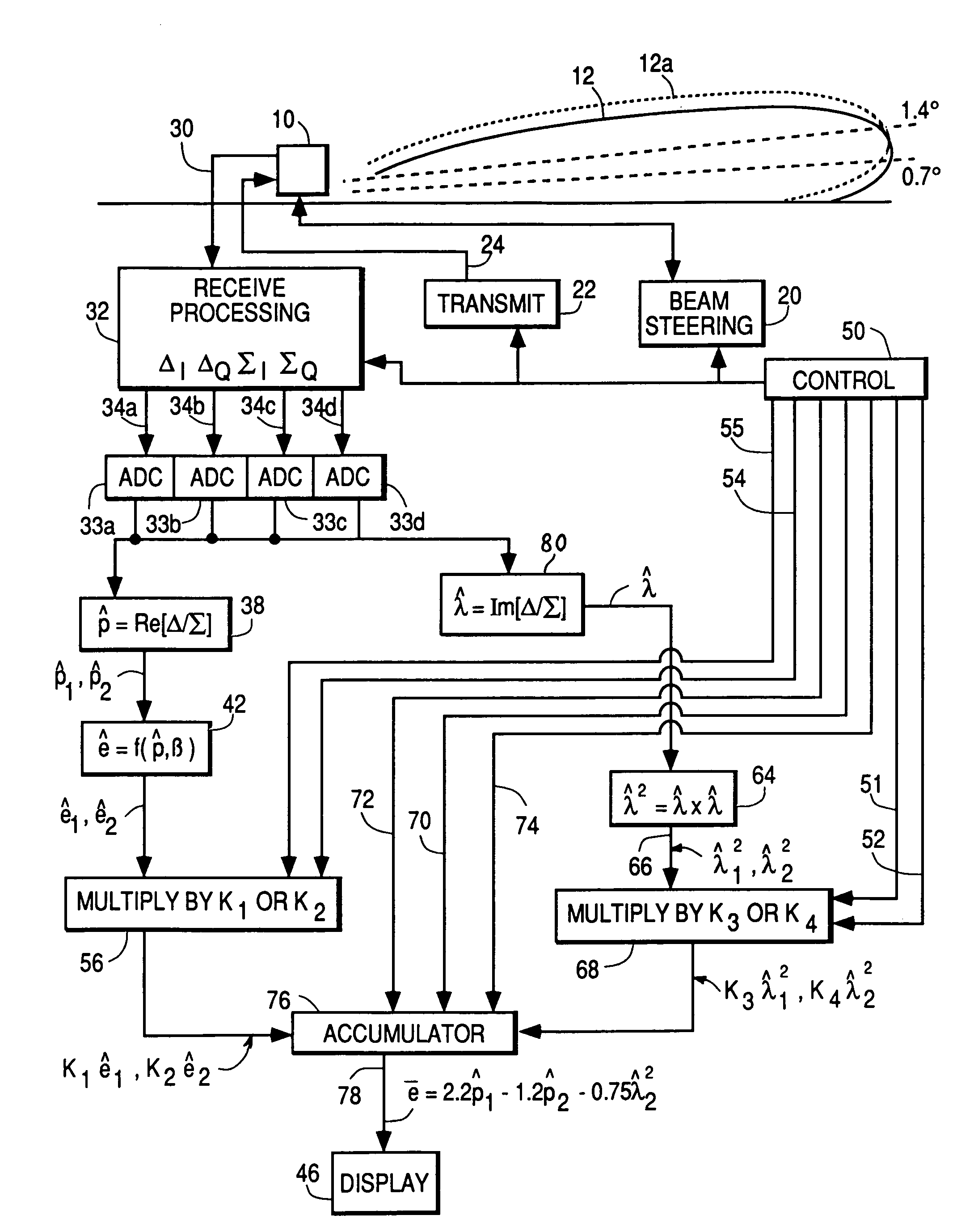
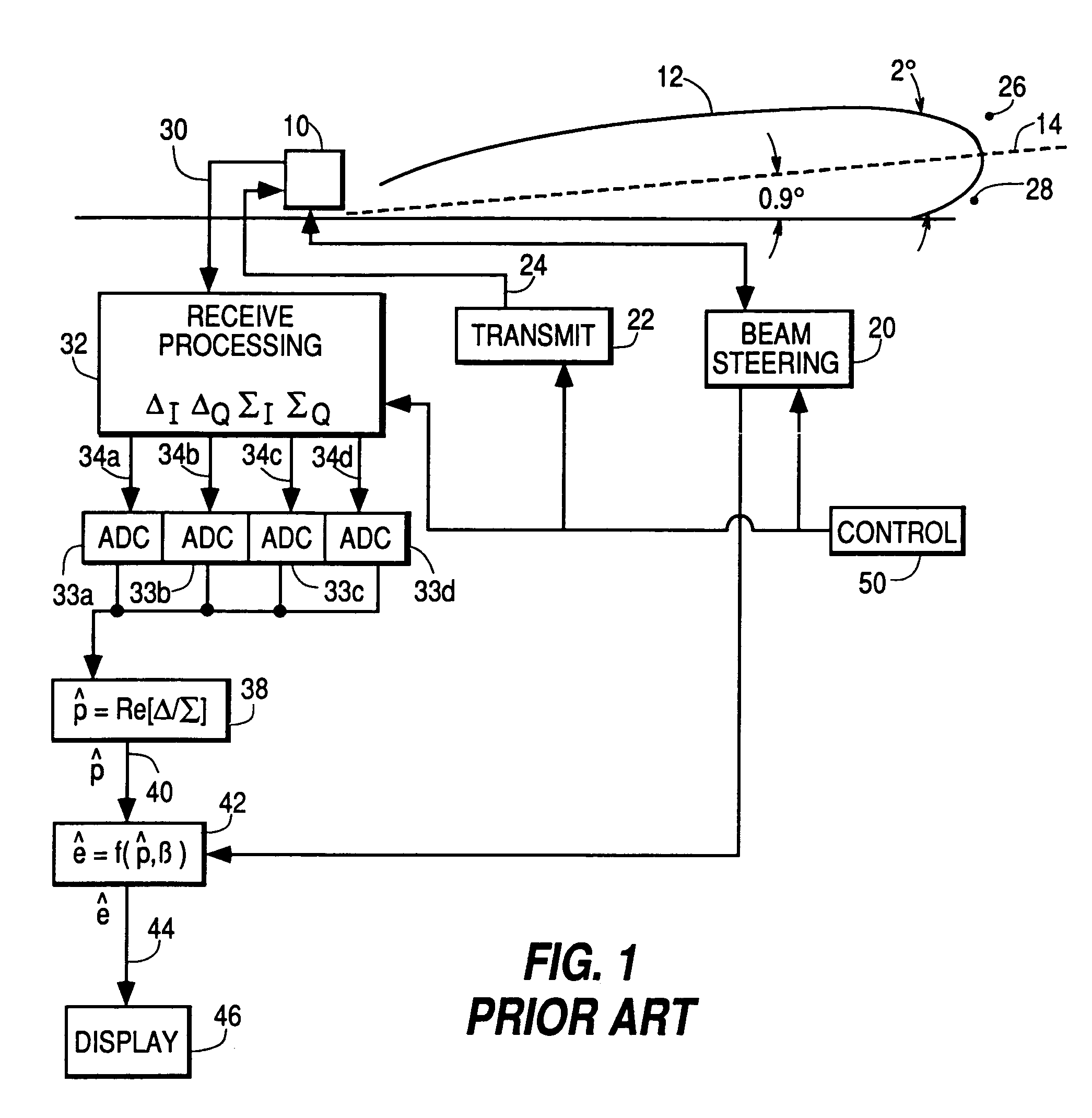
[0022]In FIG. 1, the direction in which the main beam 12 (or plural main beams, not illustrated) of array antenna 10 is directed is controlled by beam steering arrangements illustrated together as a block 20. Such beam steering arrangements control phase shifters (not illustrated) associated with antenna 10 in a predetermined manner, and are well known in the art. A transmitter illustrated as a block 22 is connected with antenna 10 by one or more paths illustrated together as a path 24 for coupling signals to antenna 10, which in turn transmits the signals in the form of electromagnetic radiation. The signals produced by transmit block 22 may be simple, constant-frequency pulses, as described for example in the text Principles of Radar, by Reintjes & Coate, published by McGraw-Hill, 1952. As an alternative, frequency-jumped pulses may be used, as described in U.S. patent application Ser. No. 266,757 filed Nov. 3, 1988, or continuous-wave signals of varying frequency may be used.

[002...


PUM


Abstract

A monopulse radar operating at low angles of elevation (LOE) receives returns from a target by a direct path and by a path including a reflection from that portion of the Earth's surface lying between the radar and the target. The surface-reflected signal tends to cause errors in the estimate of the elevation of the target. A radar system directs at least upper and lower overlapping beams at LOE toward the target for receiving returns. The upper and lower beams may be sequential or simultaneous. Real and imaginary portions of the sum (Σ) and difference (Δ) signals are generated for each beam. The monopulse estimates of elevation ê derived from the real portion of the Σ and Δ signals are processed to produce correction signals for upper and lower beams. Each correction signal is weighted and summed to correct the estimate of elevation.

Description

[0001]This invention relates to method and apparatus for improved estimates of the altitude of a target using conventional or phase monopulse radars when the target is at a low angle of elevation or near the horizon.[0002]Monopulse radar systems achieve relatively high accuracy in determining the position of a target, even though the antenna pattern may be relatively broad, by processing sum (Σ) and difference (Δ) signals. For example, the 3 dB beamwidth of a radar antenna main lobe may be on the order of 2°. A conventional radar system which depends exclusively upon a narrow beam to determine direction might, with such a beamwidth, be able to estimate the direction of the target within ±1°. By the use of monopulse signal processing techniques, accuracy improvements are possible.[0003]FIG. 1 illustrates in simplified form a prior art conventional monopulse radar system in which an antenna illustrated as 10 directs a beam, illustrated by a contour 12, which is centered along an axis ...

Claims


Application Information

Patent Timeline
Patent Type & Authority Patents(United States)
IPC IPC(8): G01S13/44
CPCG01S13/4418
Inventor REIFLER, FRANK JOSHUA RAPHAELMORRIS, RANDALL DEEN
Owner LOCKHEED MARTIN CORP
Why Eureka
Try Eureka