Ferrite phase shifter and phase array radar system

a radar system and phase array technology, applied in the direction of delay lines, antennas, waveguides, etc., can solve the problems of reducing the performance of the phase shifter and the cost of phase shifters to manufactur

Inactive Publication Date: 2008-08-26
RAYTHEON CO
View PDF7 Cites 220 Cited by
  • Summary
  • Abstract
  • Description
  • Claims
  • Application Information

AI Technical Summary

Problems solved by technology

Some planar ferrite phase shifters create an elliptically polarized wave in a ferrite substrate, instead of a circularly polarized wave, thereby reducing the performance of the phase shifter.
Such phase shifters may be expensive to manufacture.

Method used


Image

  • Ferrite phase shifter and phase array radar system
  • Ferrite phase shifter and phase array radar system
  • Ferrite phase shifter and phase array radar system

Examples


Embodiment Construction

[0009]In the following detailed description and in the several figures of the drawing, like elements are identified with like reference numerals which may not be described in detail for every drawing figure.

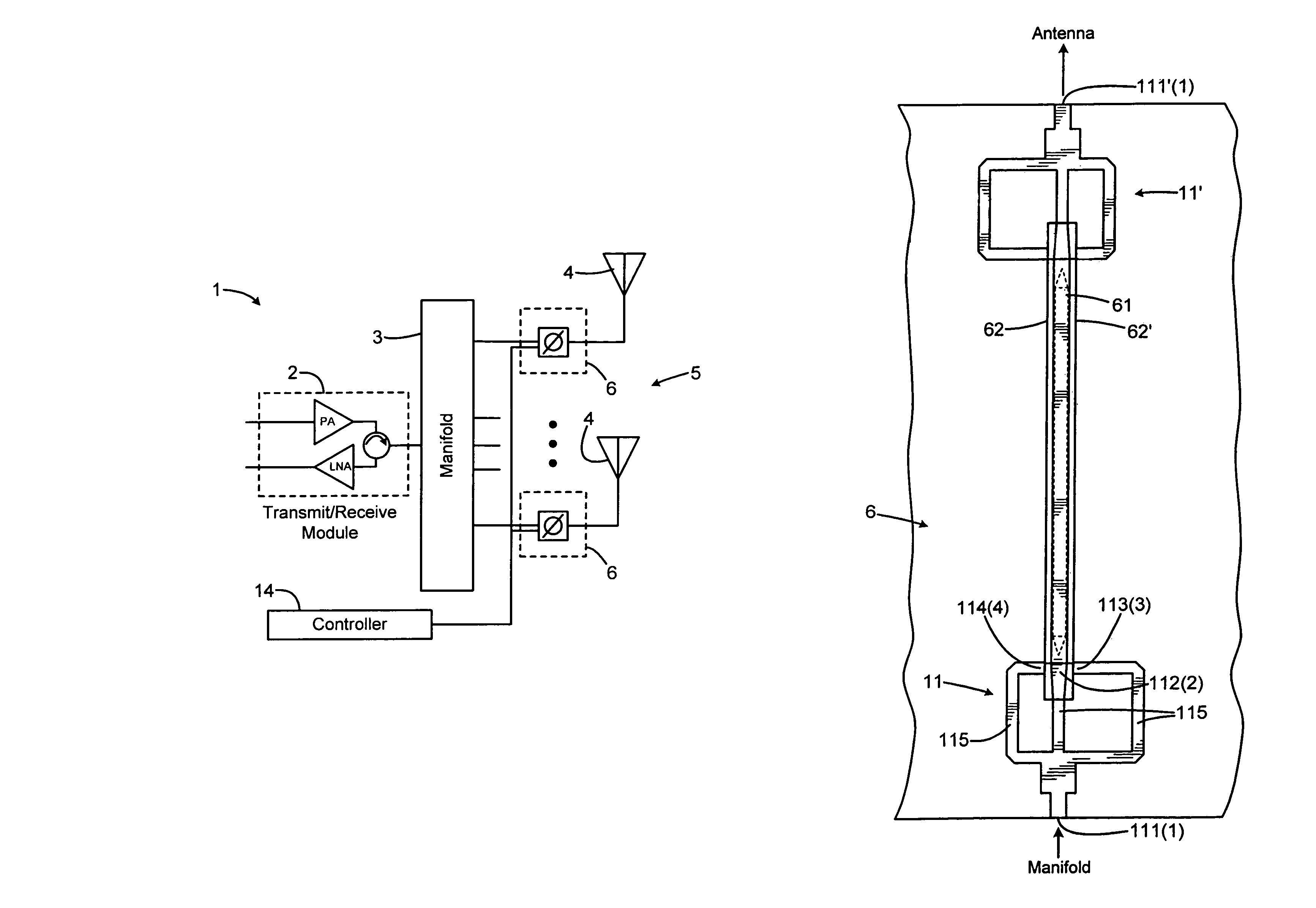
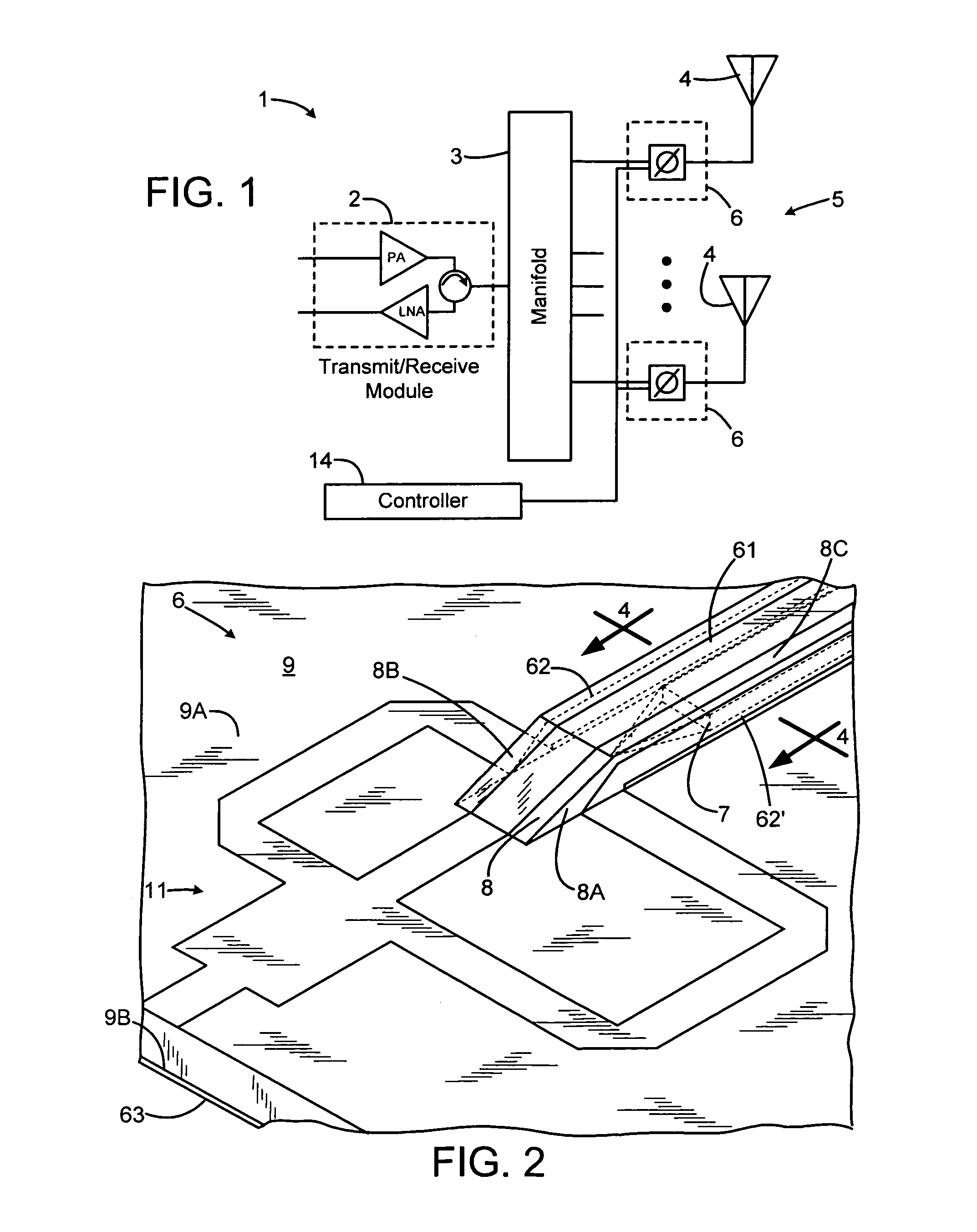
[0010]FIG. 1 is a block diagram of an exemplary embodiment of an electronically scanned phased array radar system 1. In an exemplary embodiment, the radar system 1 comprises a transmit / receive module 2, including a power amplifier PA, a low noise amplifier LNA and a circulator, a manifold 3 and a plurality of antenna elements 4. The antenna elements 4 are arranged in an array 5 and may be connected to the manifold through respective phase shifters 6. In exemplary embodiments, the phase shifters 6 individually shift the phase of signals to be transmitted by or received from the plurality of antenna elements 4 to electronically steer the array 5. A controller 14 may be provided to control the amount of phase shift applied by the phase shifters 6.

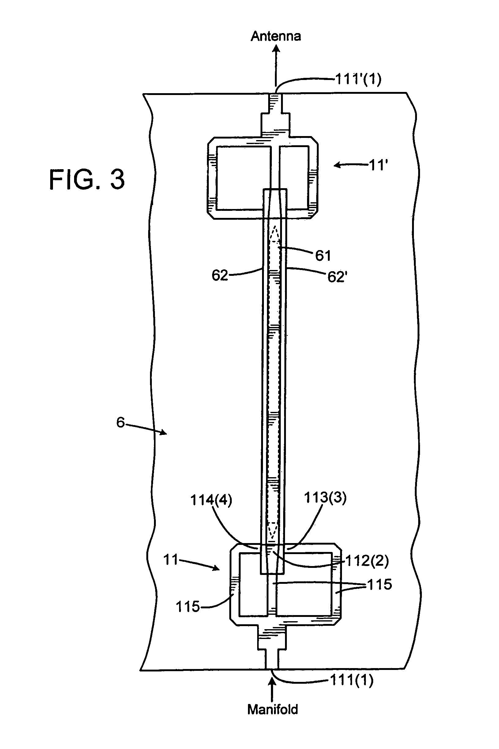
[0011]FIGS. 2, 3 and 4 illustrate is...


PUM


Abstract

A phase shifter comprises a substrate, a ground plane formed on a first surface of the substrate, a support structure positioned on a second surface of the substrate opposite the first surface, three parallel, non-co-planar microstrip lines supported by the support structure above the second surface of the substrate, a ferrite element supported by the support structure between the second surface of the substrate and the three non-co-planar microstrip lines, and means for applying a magnetic field to the ferrite element.

Description

BACKGROUND OF THE DISCLOSURE[0001]Transmission systems for electromagnetic waves, for example microwave and / or millimeter wave transmission systems, may include a phase shifter. Some embodiments of phase shifters comprise microstrips printed on a ferrite substrate. Some planar ferrite phase shifters create an elliptically polarized wave in a ferrite substrate, instead of a circularly polarized wave, thereby reducing the performance of the phase shifter. Other phase shifters are placed in metallized ferrite bars or ferrite-loaded waveguides, and / or incorporate thin quarter-wave plates at input and output ports to convert linear signals into circularly polarized signals. Such phase shifters may be expensive to manufacture.SUMMARY[0002]A phase shifter includes a substrate, with a ground plane formed on a first surface of the substrate and a support structure positioned on a second surface of the substrate opposite the first surface. Three parallel, non-co-planar microstrip lines are su...

Claims


Application Information

Patent Timeline
Patent Type & Authority Patents(United States)
IPC IPC(8): H01Q3/36H01P1/19
CPCH01P1/19
Inventor ISKANDER, MAGDY F.SORENSEN, RORY K.LEE, JAR J.KIM, HEE KYUNG
Owner RAYTHEON CO
Why Eureka
Try Eureka