Markup language and object model for vector graphics

a vector graphics and object model technology, applied in the field of computer systems, can solve the problems of visual and noticeable undesirable effects, and the limit of the traditional immediate mode model of accessing graphics on the computer system

Inactive Publication Date: 2008-08-26
MICROSOFT TECH LICENSING LLC
View PDF92 Cites 54 Cited by
  • Summary
  • Abstract
  • Description
  • Claims
  • Application Information

AI Technical Summary

Benefits of technology

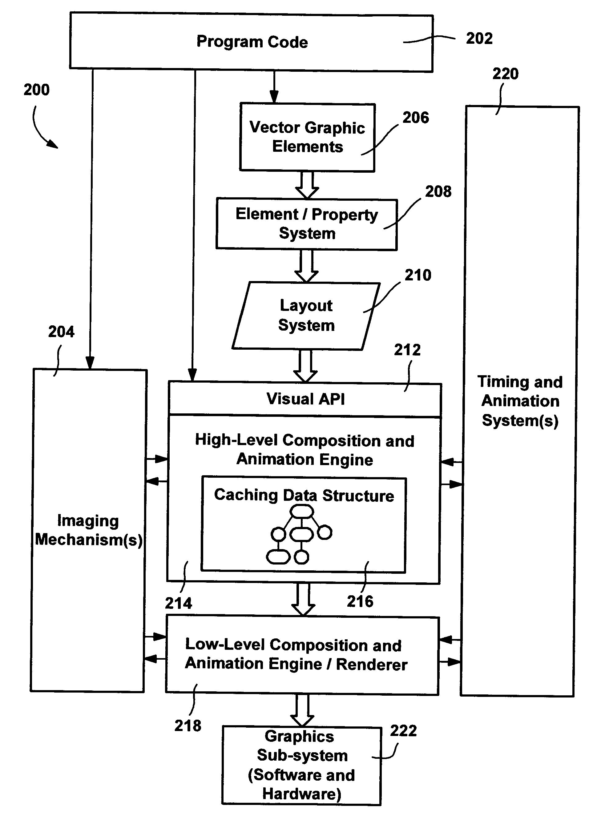
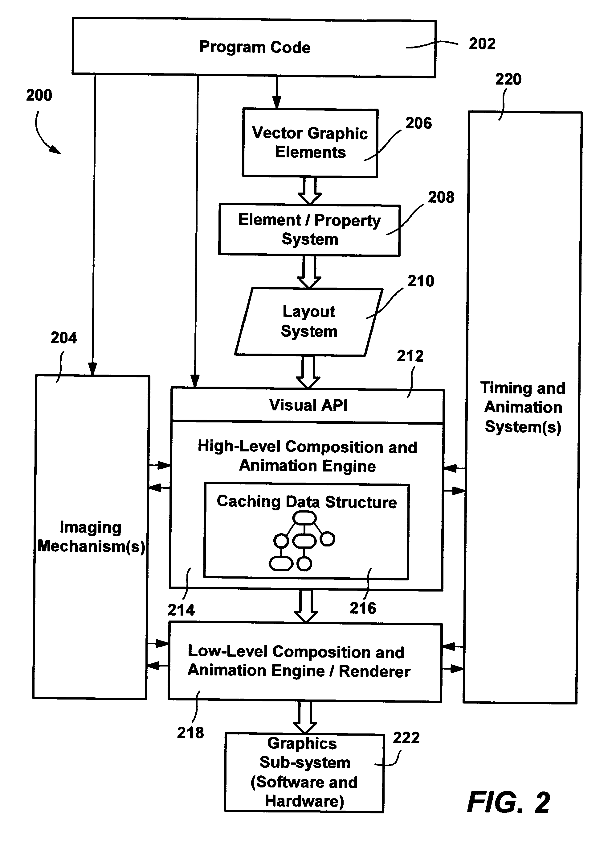
[0008]Briefly, the present invention provides an element object model and a vector graphics markup language for accessing that element object model in a manner that allows program code developers to consistently interface with a scene graph data structure to produce graphics. The vector graphics markup language comprises an interchange format for expressing vector graphics via the element object model. When interpreted, the markup is parsed into data including elements in an element tree that is translated into the objects of a scene graph data structure. At the element tr

Problems solved by technology

The limits of the traditional immediate mode model of accessing graphics on computer systems are being reached, in part because memory and bus speeds have not kept up with the advancements in main processors and/or graphics processors.
As a result, when complex graphics e

Method used


Image

  • Markup language and object model for vector graphics
  • Markup language and object model for vector graphics
  • Markup language and object model for vector graphics

Examples


Embodiment Construction

Exemplary Operating Environment

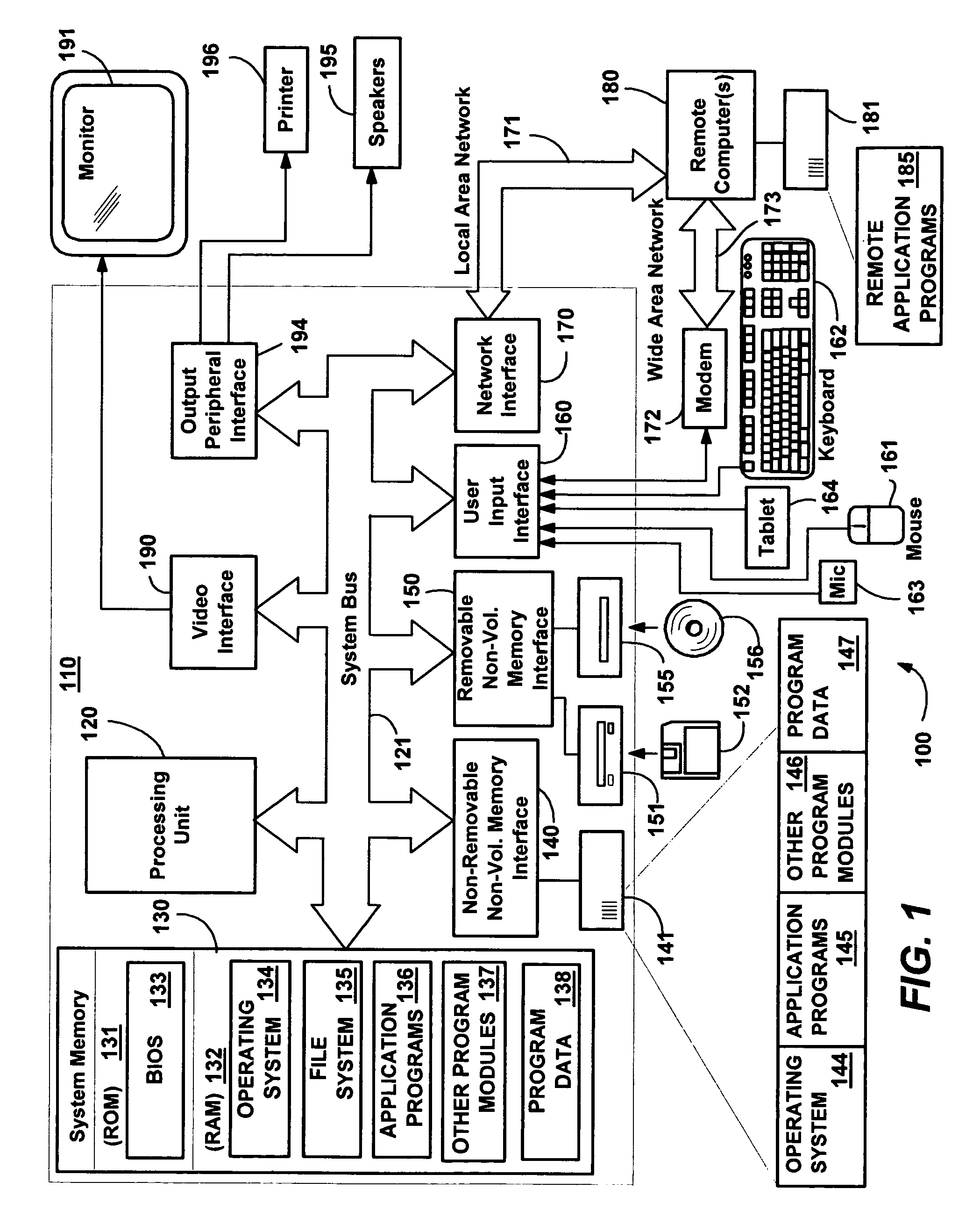
[0036]FIG. 1 illustrates an example of a suitable computing system environment 100 on which the invention may be implemented. The computing system environment 100 is only one example of a suitable computing environment and is not intended to suggest any limitation as to the scope of use or functionality of the invention. Neither should the computing environment 100 be interpreted as having any dependency or requirement relating to any one or combination of components illustrated in the exemplary operating environment 100.

[0037]The invention is operational with numerous other general purpose or special purpose computing system environments or configurations. Examples of well known computing systems, environments, and / or configurations that may be suitable for use with the invention include, but are not limited to, personal computers, server computers, hand-held or laptop devices, tablet devices, multiprocessor systems, microprocessor-based systems, set ...


PUM


Abstract

An element object model and a vector graphics markup language for using that element object model in a manner that allows program code developers to consistently interface with a scene graph data structure to produce graphics. The vector graphics element object model generally corresponds to shape elements and other elements including image and video elements that correlate with a scene graph object model of the scene graph. Markup may be parsed into data including elements in an element tree that is translated into the objects of a scene graph data structure. Other markup may be translated directly into data and calls that create the scene graph objects. The markup language provides distinct ways to describe an element, including a simple string format or complex property syntax, which may be named, enabling reuse in other locations in the markup.

Description

CROSS-REFERENCE TO RELATED APPLICATIONS[0001]The present invention is a continuation-in-part of U.S. patent application Ser. No. 10 / 401,717 filed Mar. 27, 2003.FIELD OF THE INVENTION[0002]The invention relates generally to computer systems, and more particularly to the processing of graphical and other video information for display on computer systems.BACKGROUND OF THE INVENTION[0003]The limits of the traditional immediate mode model of accessing graphics on computer systems are being reached, in part because memory and bus speeds have not kept up with the advancements in main processors and / or graphics processors. In general, the current (e.g., WM_PAINT) model for preparing a frame requires too much data processing to keep up with the hardware refresh rate when complex graphics effects are desired. As a result, when complex graphics effects are attempted with conventional graphics models, instead of completing the changes that result in the perceived visual effects in time for the ...

Claims


Application Information

Patent Timeline
IPC IPC(8): G09G5/00G06F3/00G06T13/00G06F15/16G06T11/20
CPCG06T11/20G06T17/005G06T11/60G06T2210/61
Inventor BEDA, JOSEPH S.GALLO, KEVIN T.SMITH, ADAM M.WONG, GILMAN K.SUBRAMANIAN, SRIRAM
Owner MICROSOFT TECH LICENSING LLC
Why Eureka
Try Eureka