Optical fiber ribbon splitting tool

a technology of optical fiber ribbon and tool, applied in the field of optical fiber ribbon splitting tools, can solve the problems of limited access to the ribbon, excessively difficult subset reduction, network access point, etc., and achieve the effect of compact size and effective operation

Active Publication Date: 2008-08-26
CORNING OPTICAL COMM LLC
View PDF11 Cites 3 Cited by
  • Summary
  • Abstract
  • Description
  • Claims
  • Application Information

AI Technical Summary

Benefits of technology

[0009]To achieve the foregoing and other objects, and in accordance with the purposes of the invention as embodied and broadly described herein, the present invention provides various embodiments of ribbon splitting tools for separating ribbonized optical fibers into predetermined subsets of optical fibers. In one embodiment, the tool of the present invention may be used to split a ribbon at a cable access point along a cable. The ribbon splitting tool is compact in size and capable of being used on a variety of ribbon cable types, and is capable of separating optical fibers into discrete subsets. The size and design of the tool is advantageous over tools of the prior art that are too large to effectively operate in the space defined by certain cable access points.
[0010]In one embodiment, the present invention provides a ribbon splitting tool for separating optical fibers of a ribbon accessed through a cable access point into predetermined subsets, such that one of the subsets may be spliced to tether optical fibers or connectorized. The ribbon splitting tool includes a housing having a generally T-shaped configuration. The T-shaped housing is adapted to accommodate fingers of a technician for ease of holding and manipulation of the tool. The housing defines a shaft having an interior cavity for housing a plunger and a platen operable for discretely shearing the ribbon into subsets. In exemplary embodiments, the plunger is provided with a tapered leading edge or blade and extends longitudinally throughout the housing. Further, a portion of the plunger extends outwardly from the top of the housing and is attached to an actuator. The actuator is movably attached to both the plunger and the housing and is operable for compressing the plunger, thereby producing a shearing action. In exemplary embodiments, the actuator may include a recess about its top surface for receiving a thumb of a technician. In other exemplary embodiments, the actuator is maintained in position by at least one biasing mechanism, preferably a spring, and at least one guide pin. At a distal end of the housing shaft a slot is provided for receiving and holding the cable. The cable is received such that the blade of the plunger is located about the optical fibers.

Problems solved by technology

While this subset reduction may be readily accomplished with a stand-alone ribbon, subset reduction is exceedingly more difficult at a network access point at which access to the ribbon is limited.
Conventional ribbon splitting devices are not easily applied to cable assembly applications.
Blade replacement is a time consuming procedure, moreover, an expensive inventory of different sized blades must be maintained.
Additionally, as the cover members and blades are separated, the covers may move independently of each other, consequently, the blades may become misaligned during the shearing stroke, possibly causing damage to optical fiber ribbon and optical fibers.
Further, prior art shearing devices include many parts (e.g., multiple blades), some of which are machined metal parts, the manufacture and assembly of which is expensive and time-consuming.
Still further, prior art splitting tools may not conveniently be utilized along a mid-span access point of a flat ribbon distribution cable due to the limited amount of space available.

Method used


Image

  • Optical fiber ribbon splitting tool
  • Optical fiber ribbon splitting tool
  • Optical fiber ribbon splitting tool

Examples


Embodiment Construction

[0026]The present invention will now be described more fully hereinafter with reference to the accompanying drawings in which exemplary embodiments of the invention are shown. However, this invention may be embodied in many different forms and should not be construed as limited to the embodiments set forth herein. These exemplary embodiments are provided so that this disclosure will be both thorough and complete, and will fully convey the scope of the invention to those skilled in the art. Like reference numbers refer to like elements throughout the various drawings.

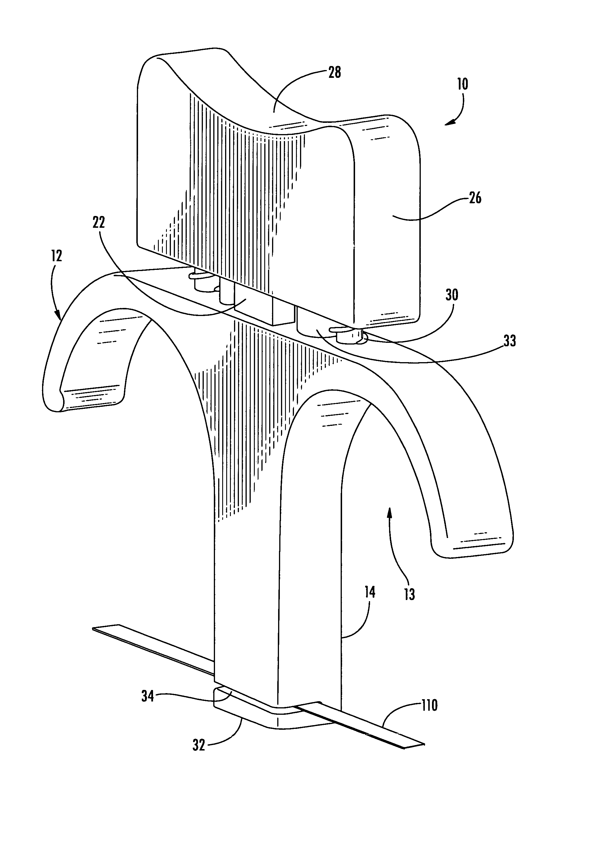
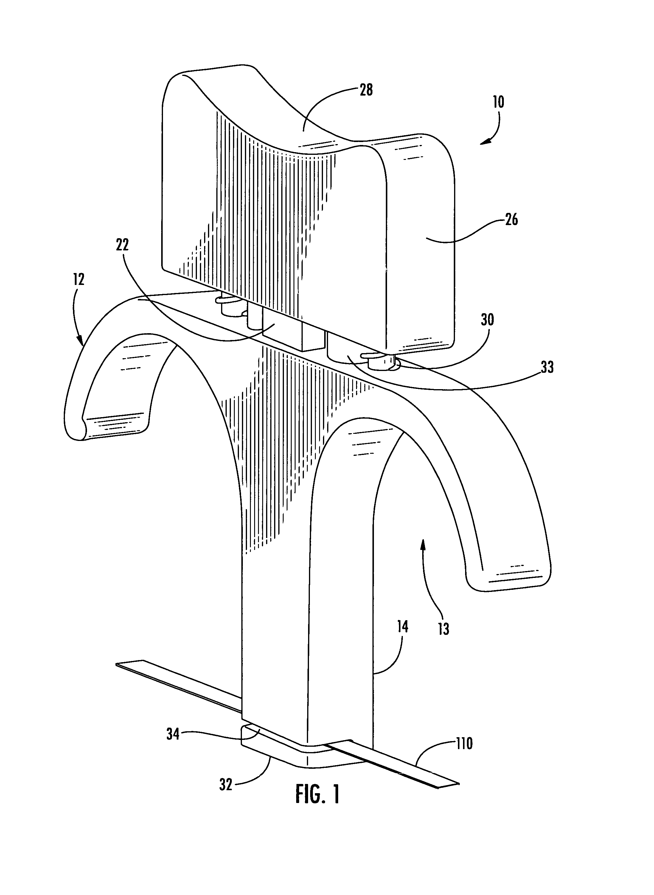
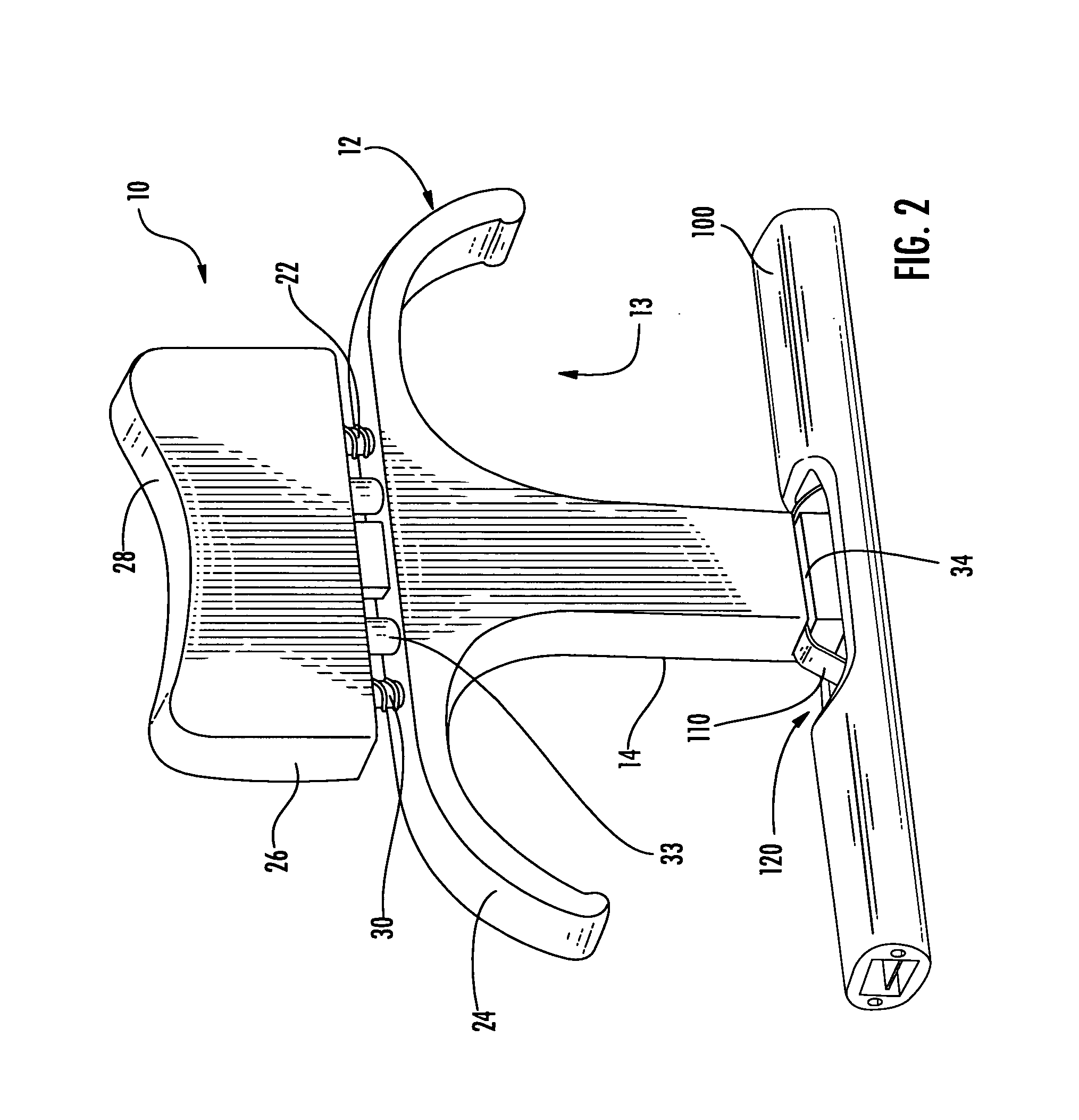
[0027]In the various embodiments described below, ribbon splitting tools for selectively separating ribbonized fibers into subsets are provided. The ribbon splitting tools may be used at a cable access point of a cable assembly in which it is desired to selectively split at least one ribbon fiber into discrete subsets having predetermined fiber numbers. Discrete subsets may be preterminated (e.g., severed at a point upst...


PUM


Abstract

An optical fiber ribbon splitting tool for selectively separating optical fibers of an optical fiber ribbon into one or more subsets of optical fibers. The ribbon splitting tool comprises a housing, a shearing device movably mounted within the housing, and an actuator for actuating the shearing device such that a subset of optical fibers is separated from the optical fiber ribbon. The shearing device may comprise a plunger having at least one shearing edge profile and a platen. A ribbon splitting tool for use at a cable access point of a fiber optic cable in which at least one optical fiber ribbon is accessible for splitting.

Description

BACKGROUND OF THE INVENTION[0001]1. Field of the Invention[0002]The present invention relates generally to optical fiber ribbon splitting tools, and more particularly, to optical fiber ribbon splitting tools operable for separating ribbons into one or more subsets of optical fibers and tools for use in splitting fiber ribbons at cable access points.[0003]2. Technical Background[0004]Fiber optic networks are being developed that include cable assemblies having network access points along the cable length for providing access to optical fibers within the cable. These cable access points serve as an entry point into a cable in order to handle, sever and split pre-selected optical fibers so that they may be withdrawn through the cable access point. The pre-selected optical fibers are typically preterminated and spliced to optical fibers of a tether, thus providing a tap or branch off of a cable used to extend the optical network. Cable assemblies including network access points are comm...

Claims


Application Information

Patent Timeline
Patent Type & Authority Patents(United States)
IPC IPC(8): G02B6/00
CPCG02B6/4498G02B6/25G02B6/567
Inventor CONRAD, CRAIG M.WHISNANT, JR., CARL M.CODY, JOSEPH T.
Owner CORNING OPTICAL COMM LLC
Why Eureka
Try Eureka