Washer

a technology of a washer and a handle, which is applied in the field of washers, can solve the problems of increasing manufacturing costs, troublesome installation of the control box b>8/b>, and short circuits, and achieves the effects of reducing the risk of fire, and preventing short circuits

Inactive Publication Date: 2008-09-02
LG ELECTRONICS INC
View PDF44 Cites 2 Cited by
  • Summary
  • Abstract
  • Description
  • Claims
  • Application Information

AI Technical Summary

Benefits of technology

[0011]Accordingly, it is an objective of the present invention to provide washing machine having an assembly of a control box and a control box receiving structure, which is designed to prevent short circuits by suppressing infiltration of washing water into the control box.
[0012]It is another objective of the present invention to provide a washing machine having an assembly of a control box and a control box receiving structure, which is designed to be easily installed and repaired.
[0013]It is still another objective of the present invention to provide an assembly of a control box and a control box receiving structure, which can reduce the manufacturing costs of the washing machine by being able to have its installation location changed.

Problems solved by technology

Such a conventional washing machine has a problem that a short circuit may be incurred due to water infiltrating the control box.
The water infiltration may cause the fire.
Furthermore, since the control box 8 is disposed on the inner wall of the cabinet 1, it is troublesome to install the control box 8 on such a location in the assembling line and repair the same.
As a result, lengthened wires are required to connect the control box 8 to the mechanical part 7 and the water supply part 6, resulting in increasing the manufacturing costs.
Furthermore, since the control box is not exposed to the air, it is likely to contact moisture causing the short circuit.

Method used


Image

  • Washer
  • Washer
  • Washer

Examples


Embodiment Construction

[0030]Hereinafter, preferred embodiments of the present invention will be described in detail with reference to the accompanying drawings.

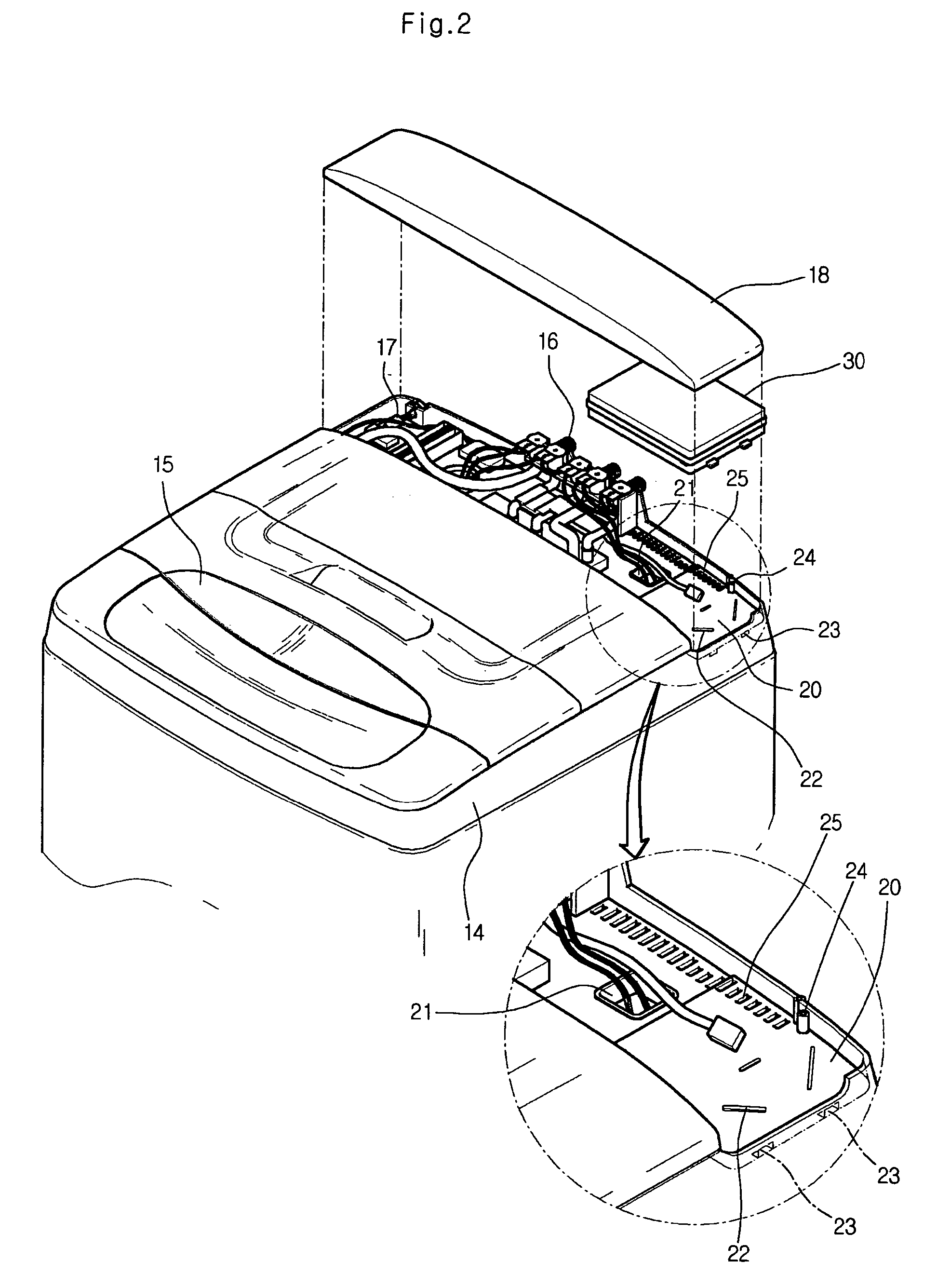
[0031]FIG. 2 shows a washing machine employing a control box assembly according to a preferred embodiment of the present invention, and FIG. 3 shows a control box according to a preferred embodiment of the present invention.

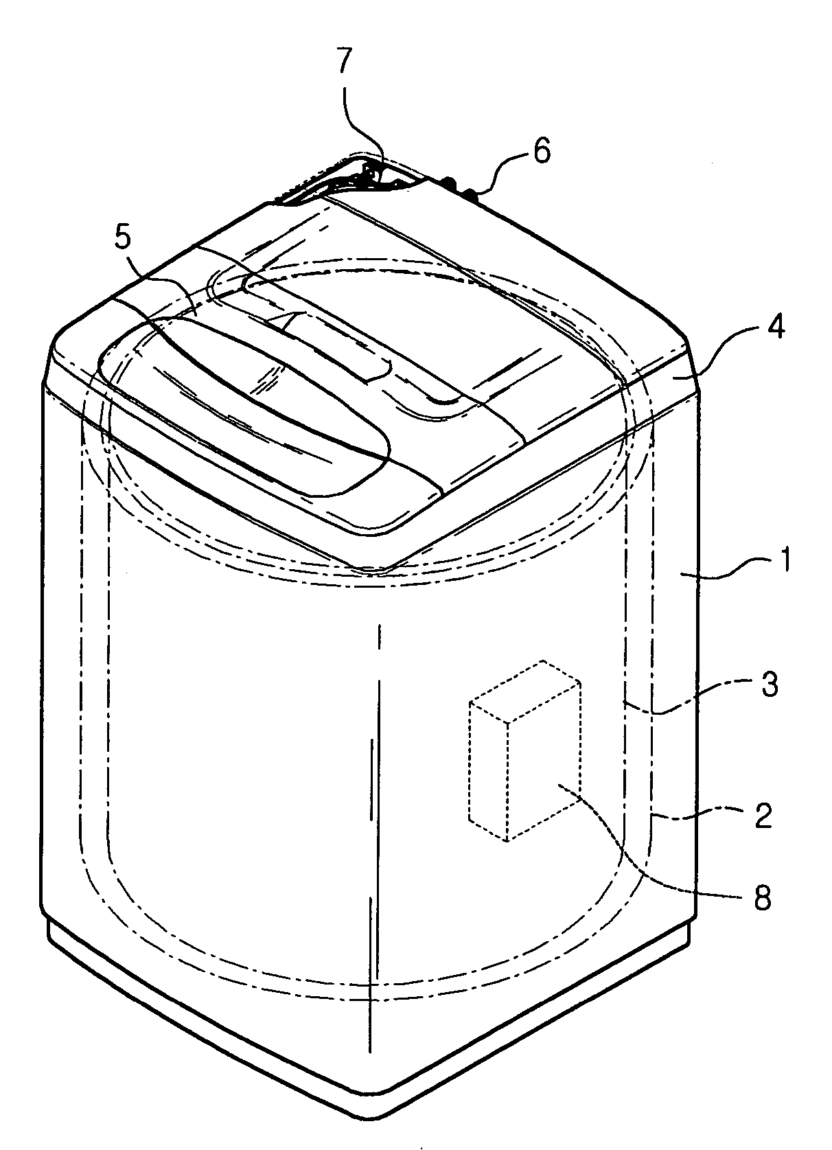
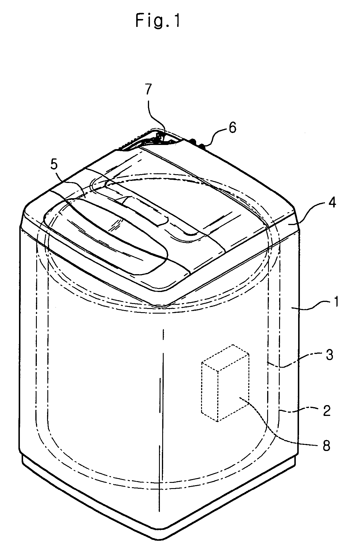
[0032]As shown in the drawings, the inventive washing machine, as in the conventional washing machine, comprises a top cover 14, a top lid 15, a water supplying part 16, and a mechanical part 17. The washing machine further comprises a protecting cover 18 covering a rear portion of the top cover 14.

[0033]The top cover 14 is provided with a control box-receiving portion 20 that is defined by indenting the rear portion of the top cover 14. That is, the control box-receiving portion 20 is defined by a bottom and a sidewall. A control box 30 is gently seated in the control box-receiving portion 20.

[0034]A complicated electrical wir...


PUM


Abstract

A washer includes an outer cabinet, a washtub disposed in the cabinet, a rotating tub rotating by a driving motor and being disposed in the washtub, a top cover disposed on top of the cabinet, the top cover being provided with an opening for loading and unloading clothes, a control box-receiving portion formed on a portion of the top cover, a control box having a circuit board for controlling the washer, the control box removably received in the control box-receiving portion, and a protecting cover for covering the portion of the top cover where the control box is received.

Description

TECHNICAL FIELD[0001]The present invention relates to a washer, and more particularly, to a control box assembly of a washing machine, which processes power switching signals and valve on / off signals through a variety of wires.BACKGROUND ART[0002]In recent years, washing machines have been designed to be fully automatic in performing washing processes such as a wash cycle, a rinse cycle, and a spin cycle. Such automatic processes are realized by turning electric Signals on and off and switching electric power supplies. The turning of electric signals and the switching of electric power supplies are controlled by a central process unit formed on a circuit board received in a control box.[0003]FIG. 1 shows a conventional washing machine.[0004]As shown in the drawing, the conventional washing machine comprises an outer cabinet 1, a washtub 2 disposed in the cabinet 1, a rotating tub 3 disposed in the washtub 2, a top cover 4 disposed on a top of the cabinet 1, a lid for opening a porti...

Claims


Application Information

Patent Timeline
Patent Type & Authority Patents(United States)
IPC IPC(8): D06F39/14A61B17/00A61B17/70A61B17/86D06F34/34D06F37/42D06F39/12F16B33/02F16B35/04
CPCD06F37/42D06F39/00D06F39/14D06F39/12D06F39/005D06F34/34D06F2103/18D06F2105/02
Inventor HEO, SEONG EUNKIM, DONG YOONLYU, JAE CHUL
Owner LG ELECTRONICS INC
Why Eureka
Try Eureka