Nozzle assembly for applying a liquid to a substrate

a technology of liquid nozzle and substrate, which is applied in the direction of photosensitive material processing, food shaping, coatings, etc., can solve the problems of large mechanical deposition force during the application of the medium, and achieve the effect of uniform flow speed and prevent the build-up of fluid pressur

Active Publication Date: 2008-09-02
INFINEON TECH AG +1
View PDF9 Cites 2 Cited by
  • Summary
  • Abstract
  • Description
  • Claims
  • Application Information

AI Technical Summary

Benefits of technology

[0010]In a particularly preferred embodiment of the invention, a downwardly widening gap is formed between the nozzle body and the guide plate, this thereby assisting the formation of a homogeneous liquid film on the guide plate in a direction towards the lower edge. In order to simplify the construction of the gap, the latter is preferably formed by a flat surface of the nozzle body and a flat surface of the guide plate which form an acute angle therebetween.
[0024]In a preferred embodiment of the invention, a mechanism is provided for adjusting the spacing between the lower edge of the guide plate and the substrate. The head or height of fall of the liquid film can thereby be changed in order to adjust the force with which the liquid is applied to the substrate. In a further embodiment of the invention, the lower edge of the guide plate is a sharp edge in order to provide a defined break-away edge at the lower edge of the guide plate. This thereby ensures that the liquid film will run-off in a defined manner and, moreover, a change in the direction of flow of the liquid when leaving the guide plate is prevented.

Problems solved by technology

However, it is still necessary to use high speeds of flow in order to enable the medium to be applied as simultaneously as possible, this thereby again resulting in a large mechanical deposition force during the application of the medium.

Method used


Image

  • Nozzle assembly for applying a liquid to a substrate
  • Nozzle assembly for applying a liquid to a substrate
  • Nozzle assembly for applying a liquid to a substrate

Examples


Embodiment Construction

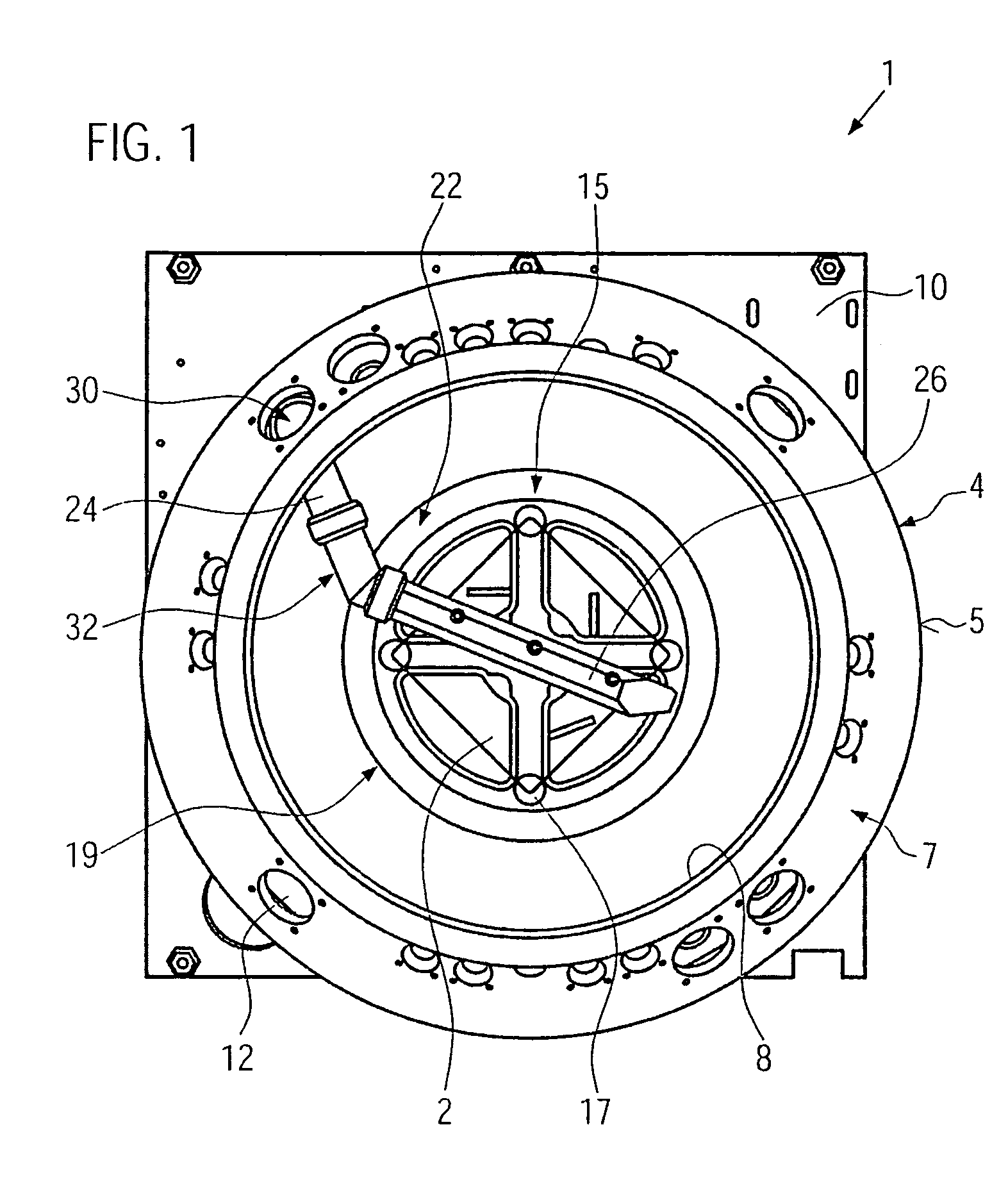
[0035]FIG. 1 shows a schematic plan view of a device 1 for treating masks 2 used for the production of semiconductor wafers. The device 1 includes a treatment container 4 having a side wall 5 which is conically tapered at least in an upper portion 7 thereof and thereby forms an upper, round input / output opening 8. The base of the treatment container 4 is formed by an appropriate base plate which is fixed together with the side wall 5 to a mounting plate 10. The upper input / output opening 8 is adapted to be closed by an appropriate cover which is not illustrated in detail. A plurality of through holes 12 providing a feed passage for different treatment systems, in particular feed lines for different liquids, is provided in the conical part 7 of the side wall 5.

[0036]A rotatable receiver or seating mechanism 15 is provided inside the treatment container 4, said mechanism comprising four receiver or seating elements 17 in accordance with FIG. 1. The seating mechanism 15 is rotatable by...


PUM

PropertyMeasurementUnit
acute angleaaaaaaaaaa

Abstract

The aim of the invention is to achieve a rapid, homogeneous application of a liquid with as little force as possible to a substrate. To achieve this, the invention provides a nozzle assembly (22) for applying a liquid to a substrate, said assembly having a nozzle body (26) comprising a plurality of nozzles (36) that are substantially arranged in a line and a guide plate (28) that extends essentially in a vertical direction with a straight lower edge. According to the invention, the nozzles (36) above the lower edge are directed towards the guide plate (28) in such a way that a film of liquid forms on the guide plate (28) and flows over the lower edge (64).

Description

BACKGROUND OF THE INVENTION[0001]The present invention relates to a nozzle assembly for applying a liquid to a substrate.[0002]In many fields of application, especially those for producing wafers and masks during the treatment of a substrate, it is necessary to deposit a layer of liquid such as a developer for example, on the wafer or the mask.[0003]In the past, this has been done using a single nozzle which was directed towards the substrate and was swept or scanned over the mask or the wafer in raster-like manner in order to wet the entire surface of the substrate. As an alternative, consideration has also been given to the use of several mutually adjacent nozzles which were directed towards the surface of the substrate and wetted the entire substrate in the course of a single sweep.[0004]If the liquid being applied is, for example, a liquid developer which is used for the development steps in a micro-lithographic process, it is important for the quality of the final product to en...

Claims


Application Information

Patent Timeline
Patent Type & Authority Patents(United States)
IPC IPC(8): B05C3/02G03F7/30B05B1/14B05C5/00H01L21/027
CPCB05C5/005G03F7/16G03D5/04B05D1/04
Inventor SCHWERSENZ, ANATOLSAULE, WERNERNORING, ANDREASDRESS, PETERBURGEL, CHRISTIANTSCHINKL, MARTINSTROBL, MARLENE
Owner INFINEON TECH AG
Why Eureka
Try Eureka