Vane-type cam phaser having increased rotational authority, intermediate position locking, and dedicated oil supply

a cam phaser and cam shaft technology, applied in mechanical equipment, machine/engine, valve drives, etc., can solve the problems of unfavorable locking pin re-engagement, uncertain re-engagement of the pin end with the stator seat, and low oil pressure to reliably actuate the locking pin, so as to prevent accidental pin ejection and remove oil resistance to entry

Active Publication Date: 2008-09-09
DELPHI TECH IP LTD
View PDF27 Cites 35 Cited by
  • Summary
  • Abstract
  • Description
  • Claims
  • Application Information

AI Technical Summary

Benefits of technology

[0017]Preferably, the seat and the ends of the locking pin are vented by appropriately-formed passages in the rotor and stator, which are aligned when the rotor is at the selected locking angle, to remove oil resistance to entry of the pin into the seat.
[0018]Preferably, the pin is cylindrical and the seat is square-sided to prevent accidental pin ejection from pressure variations in C1 and C2.

Problems solved by technology

A problem in such prior art phasers is that the pressure requirements and timing of advance and retard can be quite different than those for pin movement under some engine operating conditions.
It is well known in the art, for example, that a locking pin may become stuck in lock mode when chamber pressure increases faster than the pin can respond, causing the rotor to try to rotate before the locking pin is fully retracted, thereby binding the pin in the locking seat.
Further, oil pressures may be too low to reliably actuate the locking pin, even when the rotor is properly actuated.
A problem in some prior art phasers is that re-engagement of the pin end with the stator seat can be uncertain.
If the pin fails to fully engage the seat, the pin can be forced out of the seat during engine operation when locking engagement is required, which is highly undesirable.
However, such a non-cylindrical pin can be forced from the seat by pressure fluctuations in the phaser advance and retard chambers caused by torque reversals imposed on the camshaft during valve opening and closing events.
Because the rotor is stopped by the stator, further advance or retard, should it be desired under special circumstances, is not possible in a prior art phaser.
Further, a prior art phaser is not adapted for rotor-locking an intermediate authority position, as would be required.
Prior art phasers are not capable of this beneficial extended authority.

Method used


Image

  • Vane-type cam phaser having increased rotational authority, intermediate position locking, and dedicated oil supply
  • Vane-type cam phaser having increased rotational authority, intermediate position locking, and dedicated oil supply
  • Vane-type cam phaser having increased rotational authority, intermediate position locking, and dedicated oil supply

Examples


embodiment 200

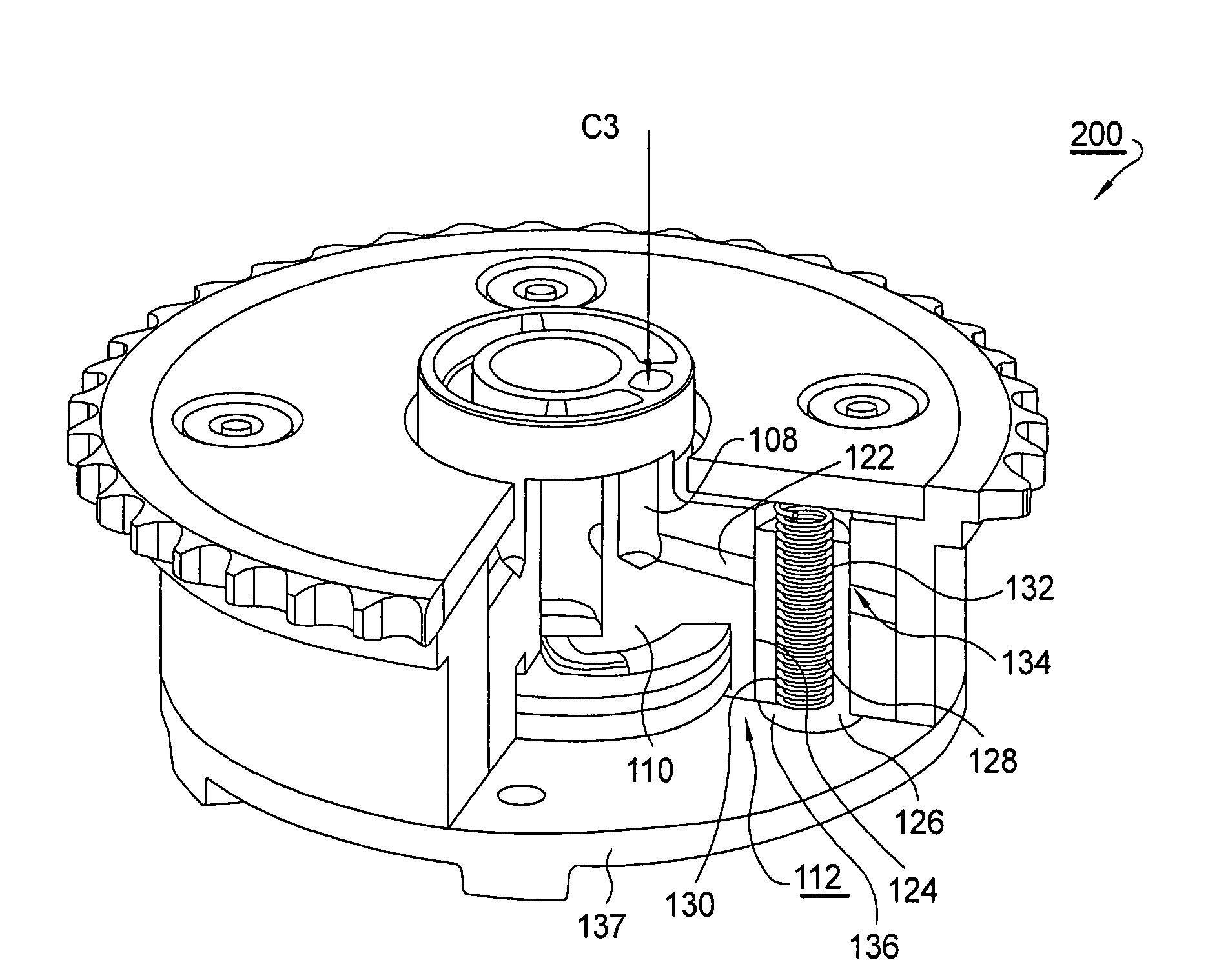
[0043]Referring to FIGS. 6 through 8, in second and currently-preferred embodiment 200, longitudinal gallery 108 is radially intersected by passage 122 extending through a bore 124 in a rotor vane slidably supportive of locking pin 126 and internal return spring 128. Locking pin 126 has a first diameter over the locking portion 130 thereof, and a larger second diameter over an actuating portion 132 thereof, there being a shoulder 134 therebetween. Likewise bore 124 is shouldered to be full-fitting to both first and second pin portions 130,132. Thus, C3 oil provided via passage 122 acts upon shoulder 134 to urge pin 126 from stator seat 136, as shown in FIG. 7 (“oil pressure to unlock, spring to lock”). Locked position is shown in FIG. 8.

[0044]Note that in both improved embodiments 100,200, the phasing action of the rotor within the phaser is controlled conventionally by independent C1 and C2 oil supplies (not shown) as in prior art phaser 10. The invention is directed to providing a...

embodiment 100

[0048]For embodiment 100, the valve logic is simply reversed.

[0049]Preferably, locking pin 126 is cylindrical and seat 136 is square-sided such that there is no vector to assist in urging the pin from the seat in response to any stray pressure pulses, and further to assure that the pin remains in locked mode if only partially inserted into seat 136.

[0050]Because the motion of the lock pin in the direction opposite to C3 pressure is solely in response to compression (embodiment 200) or extension (embodiment 100) of spring 128, care should be taken to assure that rapid motion of the pin is not impeded by residual oil in seat 136 and against shoulder 134. Therefore, an active oil vent path is preferably provided.

[0051]Referring to FIGS. 9 and 11-13, a first vent passage 150 extends axially of the rotor hub in communication with first end 120 of locking pin 126. When the rotor is in position for locking engagement to stator seat 136, first passage 150 is aligned and communicates with bo...


PUM


Abstract

A vane-type camshaft phaser having a rotational authority between 40 crank degrees before TDC and 30 crank degrees after TDC. The phaser includes a stator seat formed at a rotation position intermediate between full advance and full retard. A locking pin in a vane of the rotor engages the seat, locking the rotor at the intermediate position. The pin is disengaged by pressurized engine oil independent of oil flows for advance and retard of the rotor. The oil is controlled by a dedicated valve. Preferably, the seat and the ends of the locking pin are vented by passages in the rotor and stator which are aligned when the rotor is at the selected locking angle to remove oil resistance to entry of the pin into the seat. To position the locking pin over the seat, phasing rate is reduced to allow time for the locking pin to engage the seat.

Description

TECHNICAL FIELD[0001]The present invention relates to vane-type camshaft phasers for varying the phase relationship between crankshafts and camshafts in internal combustion engines; more particularly, to such phasers wherein a locking pin assembly is utilized to lock the phaser rotor with respect to the stator at certain times in the operating cycle; and most particularly, to a phaser having means for locking a phaser rotor at a rotational position intermediate between full phaser advance and full phaser retard positions, wherein the phaser has an expanded range of retard action and the locking pin is controlled by a dedicated oil supply.BACKGROUND OF THE INVENTION[0002]Camshaft phasers for varying the phase relationship between the crankshaft and a camshaft of an internal combustion engine are well known. In a typical prior art vane-type cam phaser, a controllably variable locking pin is slidingly disposed in a bore in a rotor vane to permit rotational locking of the rotor to the s...

Claims


Application Information

Patent Timeline
Patent Type & Authority Patents(United States)
IPC IPC(8): F01L1/34
CPCF01L1/3442F01L2001/34453F01L2001/34463F01L2001/34469
Inventor FISCHER, THOMAS H.CUATT, DANIEL R.
Owner DELPHI TECH IP LTD
Why Eureka
Try Eureka