
Horizontal articulated robot

a robot and horizontal technology, applied in the direction of joints, thin material handling, program-controlled manipulators, etc., can solve the problem of bad outside appearance of the robot, and achieve the effect of reducing height and simple execution in a short tim

Active Publication Date: 2008-09-09
SEIKO EPSON CORP
View PDF21 Cites 33 Cited by
  • Summary
  • Abstract
  • Description
  • Claims
  • Application Information

AI Technical Summary

Benefits of technology

The present invention is a horizontal articulated robot that has mounting portions for an end effector on both the upper and lower ends of the extreme end arm. This allows for versatility in the robot's work forms and allows for the use of a single type of robot to handle various works. The working shaft is composed of a hollow rotary shaft, which allows for wiring and piping to pass through without exposing them to the outside. The mounting portions for the end effector can be composed of a flange joint or an instant mounting / dismounting type coupling means. The drive means for the working shaft can be disposed inside the extreme end arm to improve the robot's appearance and motion. The plurality of horizontal arms and joint shafts can be formed in a hollow arrangement to accommodate the wiring and piping of the end effector without exposing them.

Problems solved by technology

Further, in a robot having such a structure that wiring or piping ducts of a drive unit for driving an end effector, a working shaft, and the like are exposed in the periphery of arms, the robot is bad in an outside appearance as well as the layout of the wiring or piping ducts must be determined such that the motion of the arms is not restricted by the ducts and that the ducts do not interfere with an external object and the like.

Method used


Image

  • Horizontal articulated robot
  • Horizontal articulated robot
  • Horizontal articulated robot

Examples


embodiment 1

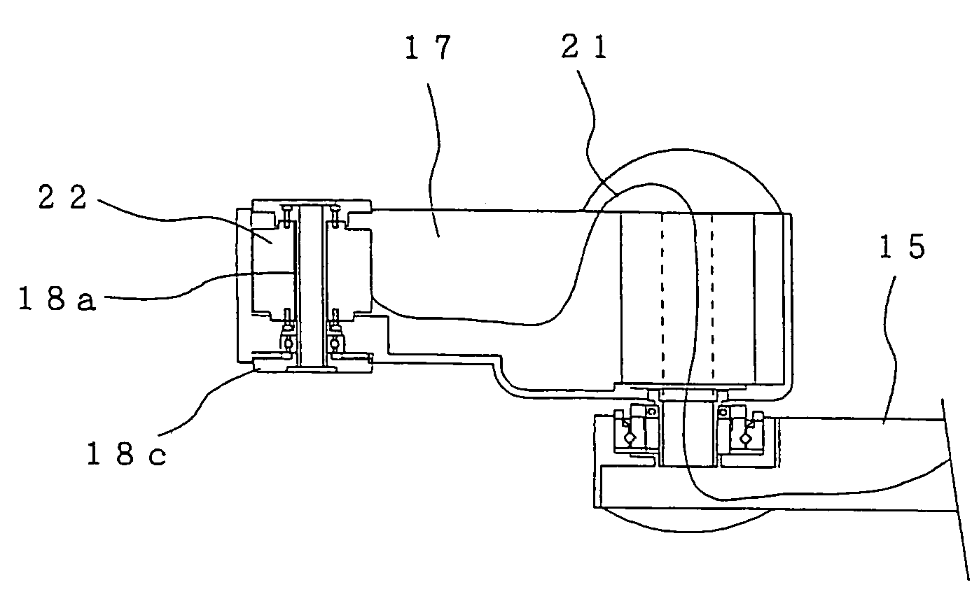
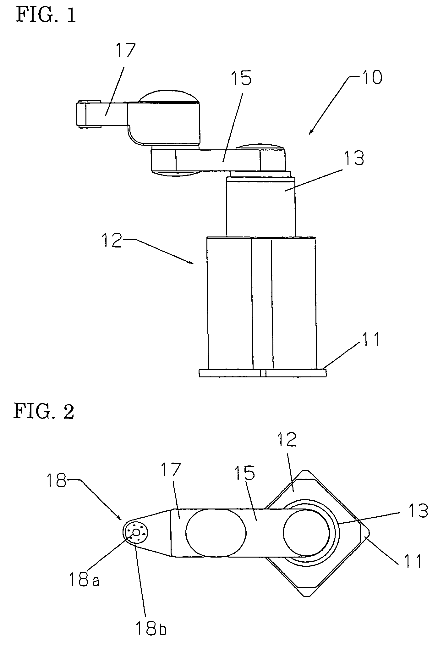
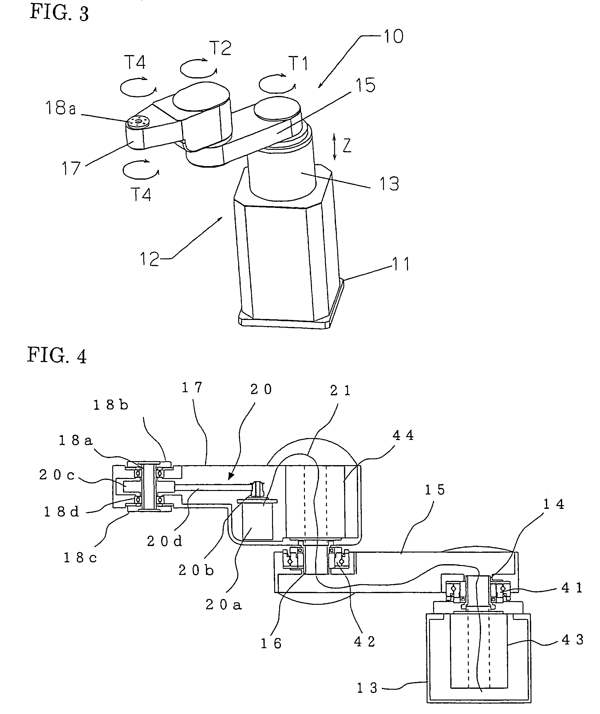
[0038]FIG. 1 is a side elevational view of a horizontal articulated robot of an embodiment 1 according to the present invention, FIG. 2 is an upper surface view of the horizontal articulated robot, and FIG. 3 is a perspective view of the horizontal articulated robot. Further, FIG. 4 is a sectional view showing an arm portion of the horizontal articulated robot.

[0039]The horizontal articulated robot 10 includes a base 11, an arm base 13 coupled with the base 11 through an up / down movement mechanism 12, a first arm 15 coupled with the arm base 13 through a first joint shaft 14, a second arm 17 coupled with the first arm 15 through a second joint shaft 16, and a working shaft 18 rotatably disposed to the extreme end of the second arm 17.

[0040]The first and second arms 15 and 17 are horizontal arms that turn in a horizontal surface, and the second arm 17 constitutes an extreme end arm. Further, the number of the arms is not particularly limited and ordinarily set between 2 and 4.

[0041]T...

embodiment 2

[0056]FIG. 8 is a sectional view of the portion of a second arm 17 in a horizontal articulated robot of an embodiment 2 according to the present invention.

[0057]Although the embodiment 1 described above shows the hollow mounting flanges 18b, 18c disposed to both the upper and lower ends of the hollow rotary shaft 18a, the embodiment 2 shows a hollow rotary shaft 18e having a hollow mounting flange disposed on one side, for example, an upper hollow mounting flange 18b. Further, the lower portion of the hollow rotary shaft 18e extends somewhat long toward the lower side of the second arm 17. A required assembly job can be executed by mounting a not shown tool (for example, screwdriver, welding torch, and the like) on the projecting portion extending downward.

embodiment 3

[0058]FIGS. 9A-9C are configurational views of a coupling means which couples a hollow rotary shaft 18a with an end effector 25 and shows an embodiment 3 according to the present invention, wherein 9A is a sectional view of a coupling state, 9B is a lower surface view on a hollow rotary shaft side, and 9C is an upper surface view on a coupling means side.

[0059]Although the hollow rotary shaft 18a is coupled with the end effector by the flange coupling in the embodiments 1 and 2 described above, the embodiment 3 is arranged such that they can be coupled with each other by screw coupling in an instant mounting / dismounting system.

[0060]More specifically, a coupling 33, which has a female screw 32 cut thereto, is disposed to a hollow cylinder 31 having an end effector 25 previously mounted on the lower end thereof. Further, the hollow cylinder 31 has a positioning key 34 disposed thereto. A coupling means on the end effector 25 side is arranged by the arrangement described above.

[0061]O...


PUM


Abstract

A horizontal articulated robot has a plurality of horizontal arms coupled by joint shafts, and a working shaft disposed at the extreme end of an extreme end arm among the horizontal arms has mounting portions of an end effector formed to both the upper and lower ends thereof. With this arrangement, there can be provided a horizontal articulated robot that can cope with various work transport forms and various types of works by one type of a robot by selectively using the upper and lower sides of a working shaft.

Description

[0001]The entire disclosure of Japanese Patent Application No. 2004-363919, filed Dec. 16, 2004, is expressly incorporated by reference herein.BACKGROUND OF THE INVENTION[0002]1. Field of the Invention[0003]The present invention relates to an horizontal articulated robot, and more particularly, to a structure of mounting portions of an end effector mounted at the extreme end of a robot arm.[0004]2. Description of the Related Art[0005]Horizontal articulated robots, which are also called scalar robots, are excellent particularly in compactness and workability and often used in industrial robots. The horizontal articulated robot has such a structure that ordinarily, first and second arms turn each in a respective horizontal plane through first and second joint shafts, respectively and an end effector such as a hand and the like is mounted on a working shaft attached to the extreme end of the second arm to thereby cause the end effector to execute a desired job such as an assembly, tran...

Claims


Application Information

Patent Timeline
Patent Type & Authority Patents(United States)
IPC IPC(8): B25J17/02
CPCB25J9/042B25J15/0052B25J19/0025Y10S414/131Y10T74/20335Y10T74/20311B25J9/04B25J9/06
Inventor AKAHA, KAZUSHIGE
Owner SEIKO EPSON CORP
Learn More