Power control of an induction machine

a technology of power control and induction machine, which is applied in the direction of electric controllers, ignition automatic control, instruments, etc., can solve the problems of restricted slip range of power regulation, asynchronous machines with slip-ring rotors, and power regulation of krzeminski, and achieve stable regulation of active power

Active Publication Date: 2008-09-09
K B ELECTRONICS INC
View PDF21 Cites 30 Cited by
  • Summary
  • Abstract
  • Description
  • Claims
  • Application Information

AI Technical Summary

Benefits of technology

[0009]It is therefore the object of the present invention to allow simple and simultaneously stable regulation of the active power and reactive power of induction machines.
[0014]According to the present invention, only one regulator is used in each case for the regulation of the setpoint variable deviation of the active power and the setpoint variable deviation of the reactive power. This regulator may be a linear regulator, such as a proportional regulator (P regulator), a proportional-integral regulator (PI regulator) having linear integrator algorithm, or a proportional-integral-differential regulator (PID regulator), or even a nonlinear regulator, such as a PI regulator having nonlinear integrator algorithm; however, all other types of regulators may also be used. This simple construction is achieved in that the active and reactive power are selected directly as the state variables which the regulation is based on. Further subordinate control loops may thus be dispensed with. Furthermore, the first and second regulator output variables are added to the feedback variables, which are selected in such a way that the state variables are at least partially decoupled and stabilization and simplification of the overall system is achieved.
[0024]According to a further preferred embodiment of the present invention, the ohmic resistance of the stator of the induction machine is neglected in the calculation of the feedback variables. The calculation of the feedback variables is thus greatly simplified. Possible imprecision of the system modeling due to neglecting the stator resistance is advantageously compensated for by the control loop.
[0025]According to a further preferred embodiment of the present invention, a stationary state is assumed in the calculation of the feedback variables. The calculation of the feedback variables is also greatly simplified by this measure. Possible imprecision of the system modeling due to assuming a stationary state is advantageously compensated for by the control loop.
[0029]Through the use of cross product and scalar product of rotor voltage and stator flux in the regulation according to the present invention, it is possible to dispense with the information about the pointer positions in relation to a specific coordinate system and allow simple regulator synthesis in spite of nonlinearity of the original system. The state of the machine is physically a function of the mutual position of the pointers which have been selected to describe the dynamics. The relationships between the pointers may also, however, be described by cross and scalar products without separate angle information. The design of the regulation may then occur in any arbitrary coordinate system fixed on the winding (e.g., fixed on the stator or rotor).
[0039]Furthermore, a computer program having commands whose execution causes a processor to perform the regulation method described above is suggested to achieve the object of the present invention. The regulation method presented is very well suitable for implementation on a processor which receives the setpoint variable deviations and the feedback variables as input variables and outputs the manipulated variable as the output variable, for example. The calculation of the feedback variables may also be implemented within the program if the processor is supplied with the required measured values of the currents, voltages, fluxes, and angular velocity of the induction machine. The computer program may be loaded into the main memory of the processor when the induction machine is put into operation and then executed, for example. Subsequent adaptation of the parameters of the regulators or possibly the feedback variables is advantageously possible.

Problems solved by technology

This behavior results in asynchronous machines having slip-ring rotors if the rotor current is oriented to the rotor flux space pointer.
However, the power regulation of Krzeminski has some disadvantages.
In addition, the slip range of the regulation is restricted.
Finally, unsatisfactory dynamics and stability of the regulation result.

Method used


Image

  • Power control of an induction machine
  • Power control of an induction machine
  • Power control of an induction machine

Examples


Embodiment Construction

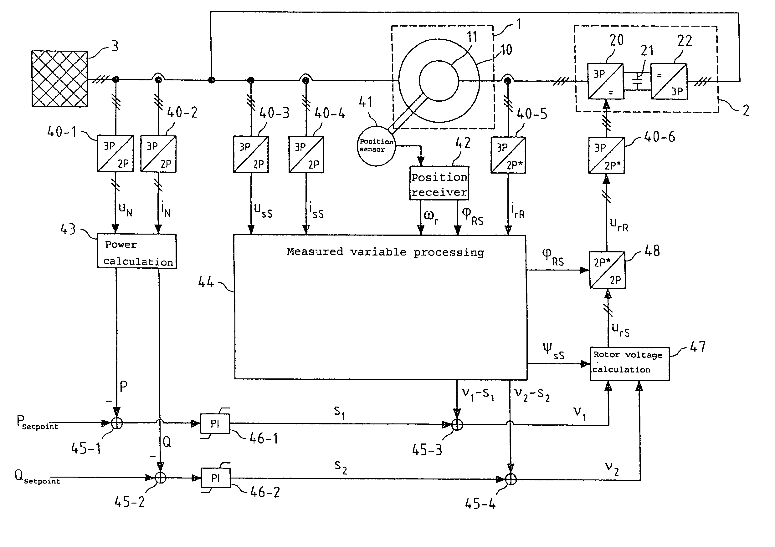
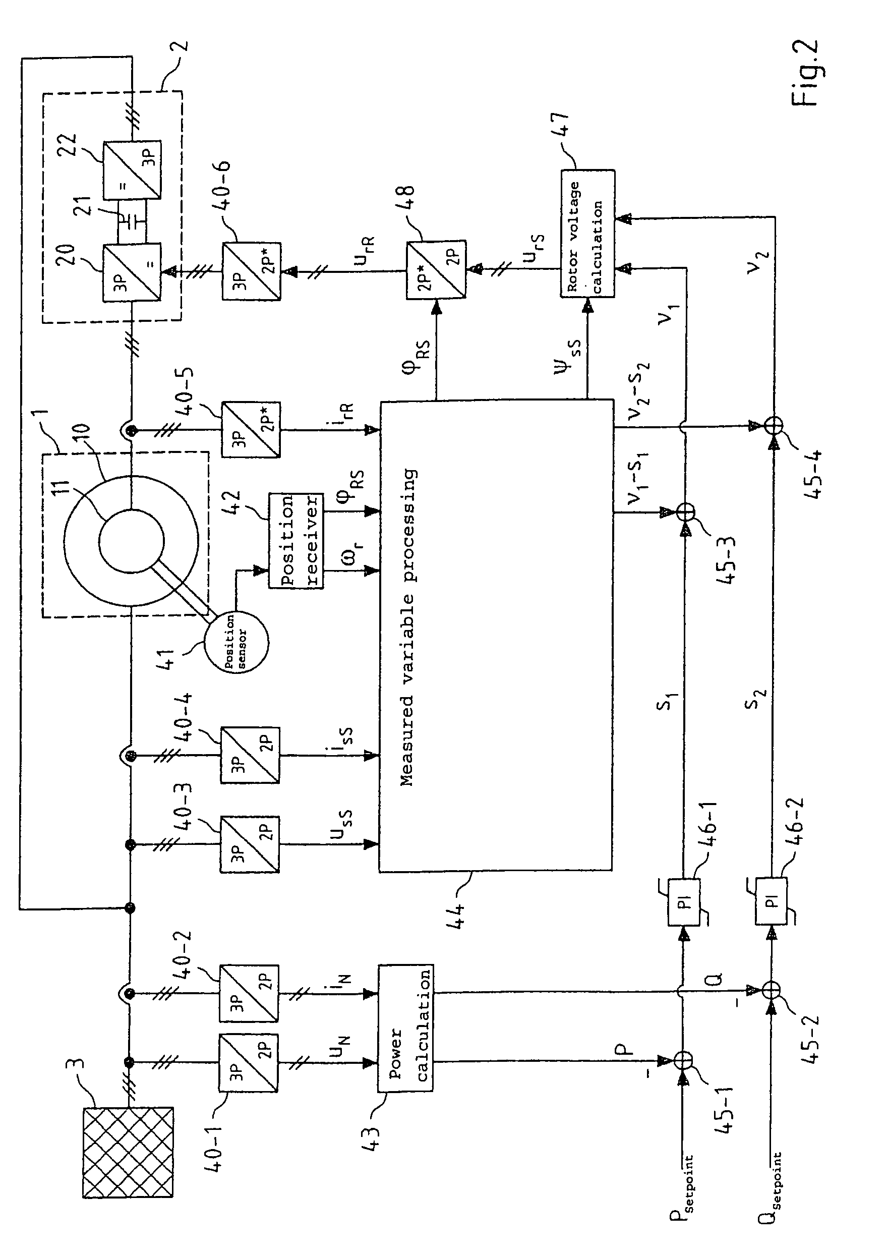
[0065]The present invention relates to the regulation of the active and reactive power of induction machines. This regulation is explained in the following using the example of a double-fed asynchronous machine having an inverter in the rotor circuit. The regulation according to the present invention is also equally suitable, however, for other induction machines, in particular for asynchronous machines having squirrel-cage rotors and full inverters in the stator circuit and for synchronous machines.

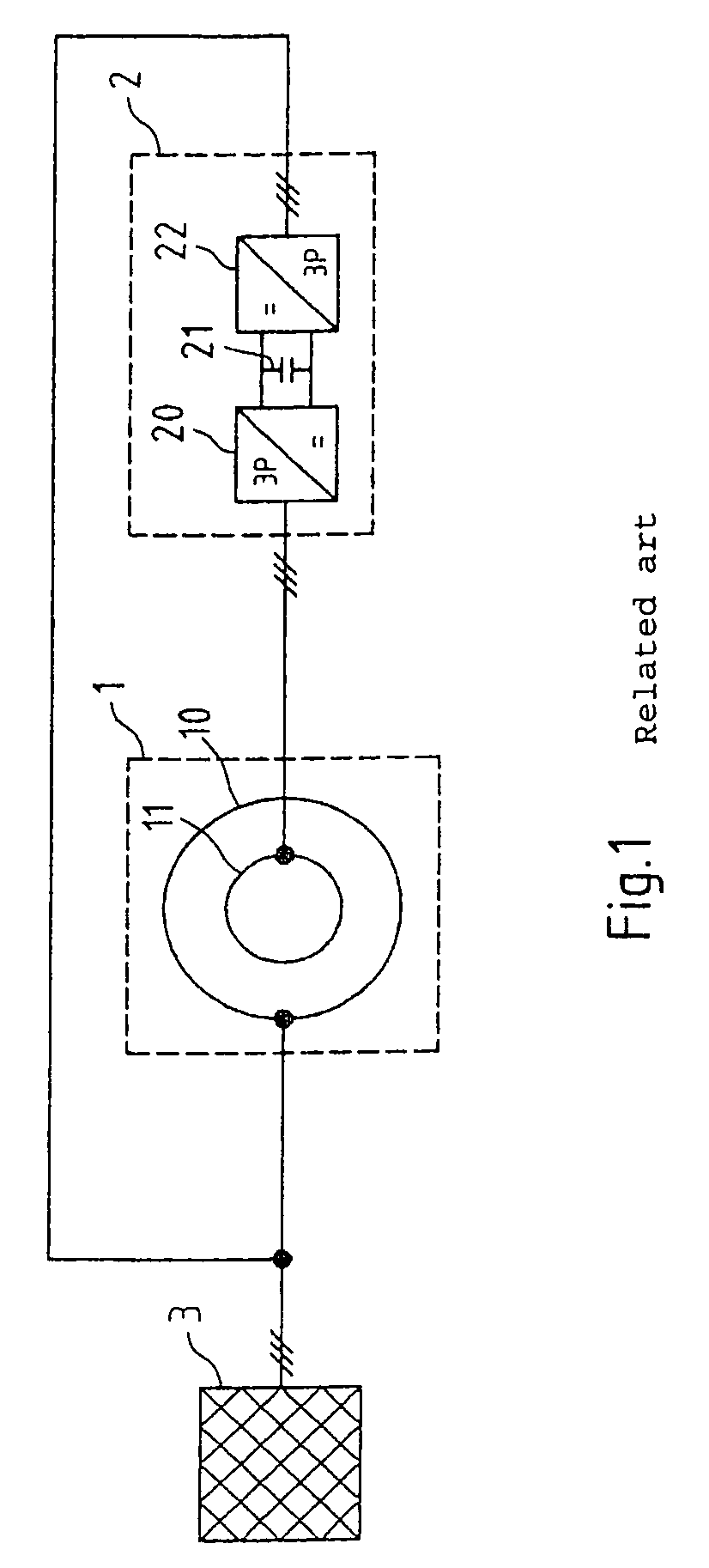
[0066]FIG. 1 shows an asynchronous machine 1 of this type, which comprises a stator 10 and a rotor 11. The rotor is connected directly or via a gear unit to a driveshaft and may thus alternately receive mechanical power (generator operation) or output mechanical power (motor operation).

[0067]The stator 10 in asynchronous machine 1 shown in FIG. 1 is connected directly to three-phase current mains 3, while the rotor 11 is connected via an inverter 2 to the three-phase mains 3. The inverte...


PUM


Abstract

Regulation of the active and reactive power of an induction machine in a coordinate system fixed on the winding, wherein a first regulator output variable is generated using a first regulator as a function of a setpoint variable deviation of the active power and a second regulator output variable is generated using a second regulator as a function of a setpoint variable deviation of the reactive power, feedback variables are added to each of the first and second regulator output variables, which are functions of at least one chronologically changing system variable of the induction machine, and a voltage or a current of the induction machine is determined as a manipulated variable without further regulation at least from the first and second regulator output variables added to the feedback variables. The feedback variables may linearize the regulation path and then allow restriction to only two simple regulators, e.g., two PI regulators. The regulation may be used in double-fed asynchronous machines.

Description

FIELD OF THE INVENTION[0001]The present invention relates to the regulation of the active and reactive power of an induction machine.BACKGROUND OF THE INVENTION[0002]Induction machines such as synchronous machines and asynchronous machines having cage or slip-ring rotors are used in manifold technical applications both in motor operation and also in generator operation. For example, asynchronous and synchronous generators are used in facilities for the decentralized generation of electrical power, such as wind power facilities, shaft generators, flywheel accumulators, and block heating power plants.[0003]At nearly constant speed, synchronous generators and asynchronous generators having short-circuit rotors are capable in principle of outputting the electrical power generated at constant voltage and frequency directly to the three-phase current mains. The advantages of such facilities are simple and robust construction, low maintenance outlay, and high reliability.[0004]Variable-spe...

Claims


Application Information

Patent Timeline
Patent Type & Authority Patents(United States)
IPC IPC(8): H02P25/28H02P9/00
CPCH02J3/1885H02P23/065H02P9/007Y02E40/32H02P23/07Y02E40/30
Inventor GENIUSZ, ANDRZEJ
Owner K B ELECTRONICS INC
Why Eureka
Try Eureka