Circuit for controlling duty cycle distortion

a duty cycle and circuit technology, applied in pulse manipulation, pulse duration/width modulation, pulse technique, etc., can solve the problems of duty cycle distortion and method also generating duty cycle errors

Active Publication Date: 2008-09-09
NAT SEMICON CORP
View PDF3 Cites 32 Cited by
  • Summary
  • Abstract
  • Description
  • Claims
  • Application Information

AI Technical Summary

Benefits of technology

[0008]Accordingly, various embodiments of the present invention disclose a circuit and method for a controlling the duty cycle of a clock signal. Embodiments of the present invention are capable of controlling a clock signal duty cycle th

Problems solved by technology

The duty cycle distortion is due in part from a clock tree supplying the clock signal to a timing controller.
The m

Method used


Image

  • Circuit for controlling duty cycle distortion
  • Circuit for controlling duty cycle distortion
  • Circuit for controlling duty cycle distortion

Examples


Embodiment Construction

[0016]Reference will now be made in detail to the preferred embodiments of the present invention, a circuit and method for controlling duty cycle of a clock signal, examples of which are illustrated in the accompanying drawings.

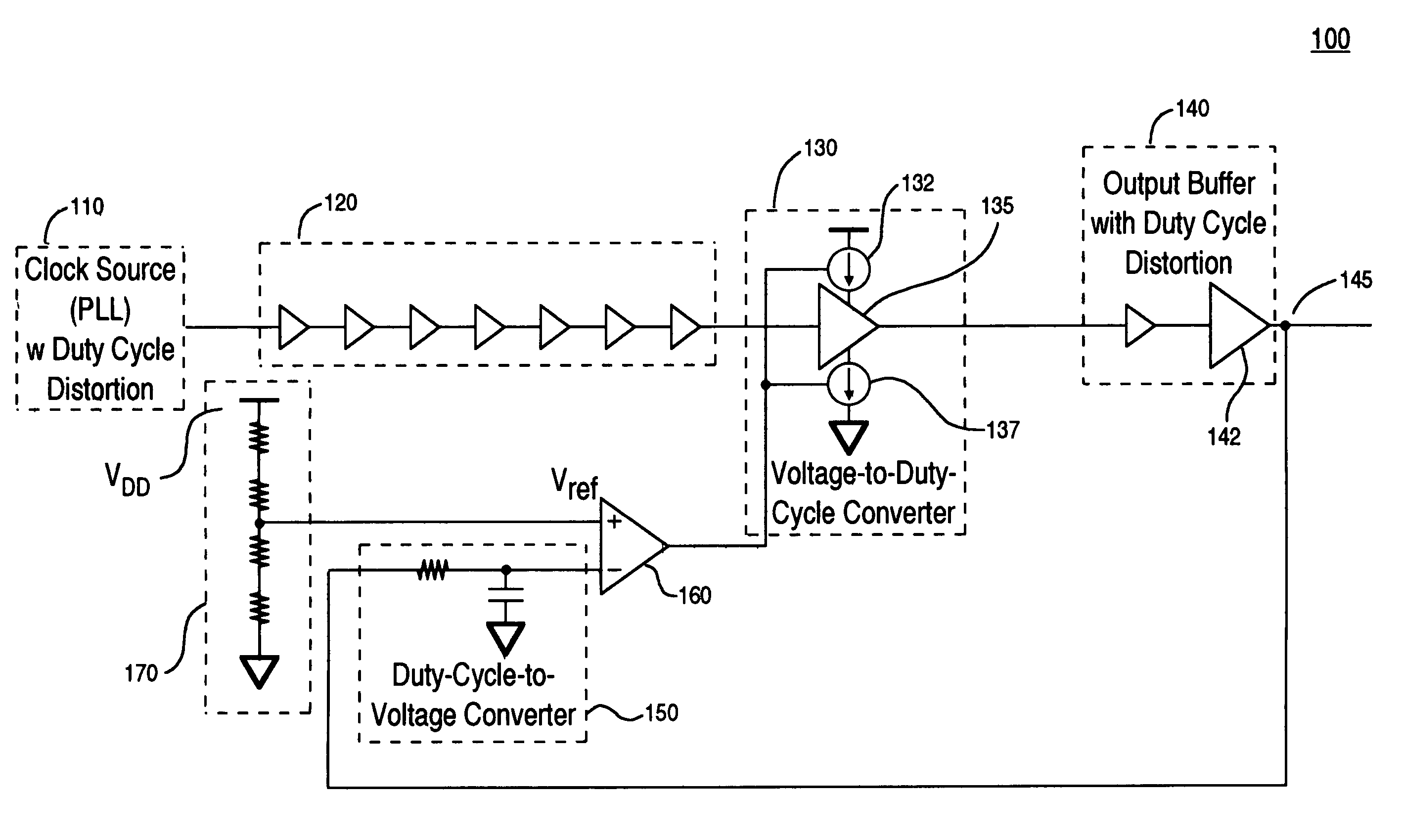
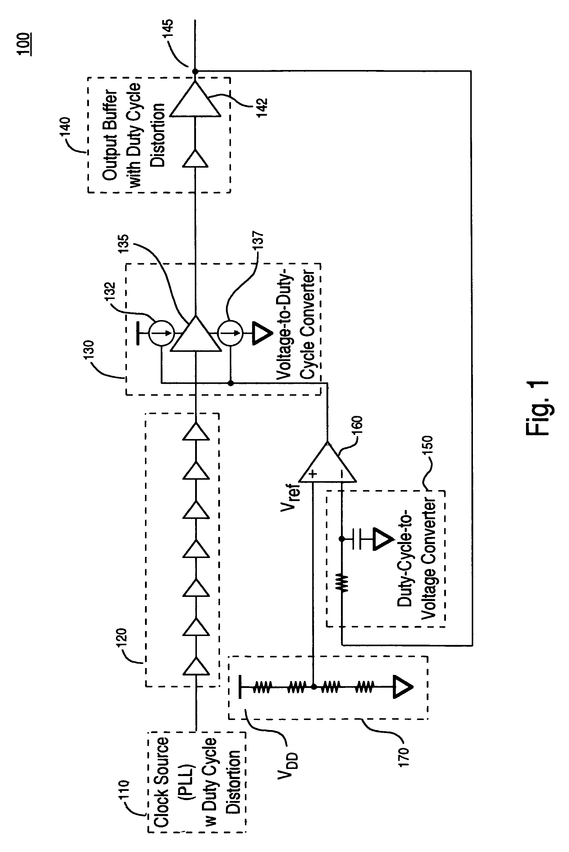
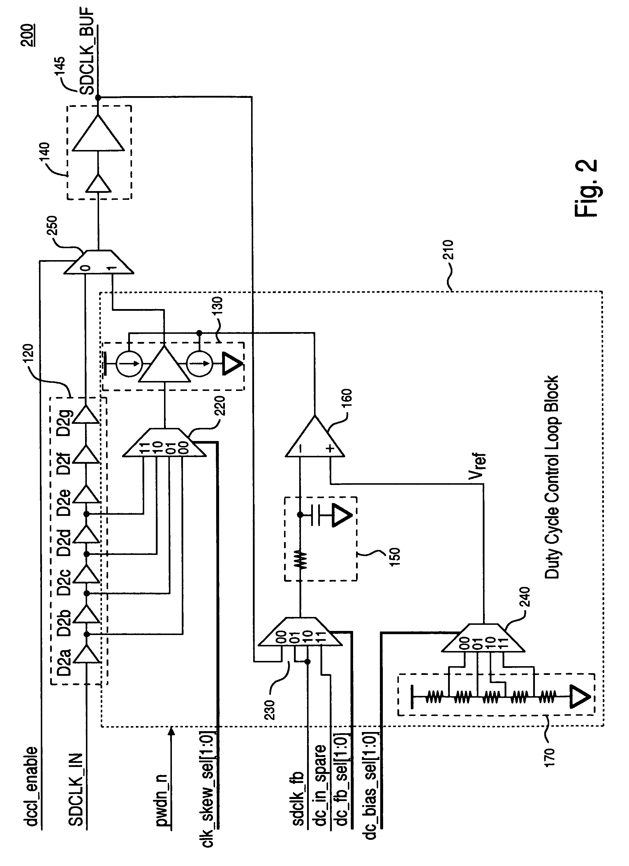
[0017]Accordingly, various embodiments of the present invention disclose a duty cycle control circuit and method for controlling a duty cycle of a clock signal. Embodiments of the present invention are capable of controlling a clock signal duty cycle through a negative feedback loop that continually measures and adjusts an output clock duty cycle. As such, high speed interface chips are able to sufficiently control the duty cycle of an output clock signal.

[0018]The following detailed description is of example embodiments of the presently claimed invention with references to the accompanying drawings. Such description is intended to be illustrative and not limiting with respect to the scope of the present invention. Such embodiments are described in sufficient...


PUM


Abstract

A circuit for controlling a duty cycle of a clock signal. The circuit includes a duty cycle control loop that includes a voltage-to-duty cycle (V-to-DC) converter, an output driver, a duty-cycle-to voltage (DC-to-V) converter, and an operational amplifier. The V-to-DC converter receives an input clock signal. The output driver is coupled to the V-to-DC converter and provides an output clock signal that is associated with a duty cycle distortion value. The DC-to-V converter converts the output clock signal to an average voltage. The operational amplifier amplifies an error between the average voltage and a reference voltage. The error is fed back to the V-to-DC converter through a negative feedback loop, wherein the V-to-DC converter adjusts a duty cycle of the input clock signal based on the error.

Description

BACKGROUND OF THE INVENTION[0001]1. Field of the Invention[0002]Embodiments of the present invention relate to the field of timing controllers. More particularly, embodiments of the present invention relate generally to duty cycle control of a clock signal through a negative feedback control loop.[0003]2. Related Art[0004]Liquid crystal displays (LCDs) are important to the television market. However, pushing LCDs to the next generation by simply scaling existing LCD monitor panels to wider formats (e.g., 16:9 HDTV) and larger formats is a complicated endeavor. A number of television requirements push beyond conventional state-of-the art monitors. For instance, response time, brightness, contrast, color envelope, color temperature, and progressive scan-and-hold issues require a re-engineering of the monitor solution.[0005]Specifically, LCD televisions bring forward a completely new set of challenges that are broader than simple data signaling issues. The demand for up to HDTV formats...

Claims


Application Information

Patent Timeline
IPC IPC(8): H03K3/017
CPCH03K5/1565
Inventor SIMON, DANIEL L.
Owner NAT SEMICON CORP
Why Eureka
Try Eureka