
Carbon dioxide absorber canister attachment

a carbon dioxide absorber and canister technology, applied in the field of anesthesia systems, can solve the problems of user's failure to notice the missing canister, disassembly, and removal of caregiver's attention, and achieve the effects of accurate connection, repeated use, and convenient us

Inactive Publication Date: 2008-09-16
GENERAL ELECTRIC CO
View PDF15 Cites 15 Cited by
  • Summary
  • Abstract
  • Description
  • Claims
  • Application Information

AI Technical Summary

Benefits of technology

"The present invention provides a mechanism for easily and securely connecting and disconnecting a carbon dioxide absorption canister to a patient breathing circuit on a ventilator. The mechanism includes a cradle that can hold the canister and is positioned to remove carbon dioxide from the breathing gas. When the canister is removed, a CO2 bypass mechanism is activated to close the breathing system. The mechanism also includes a mounting bracket and a hinge-connected cradle that can be easily attached and detached. The mechanism provides a visual indication that the canister is removed, which reduces the risk of forgetting to reattach it. Overall, the invention improves the reliability and safety of the breathing circuit."

Problems solved by technology

However, distractions can occur that remove the caregiver's attention from installing a new canister.
Once attention is regained, the user may fail to notice the missing canister because the system appears to be functioning normally.
If the system continues to operate without the CO2 bypass, serious medical complications to the patient can occur.

Method used


Image

  • Carbon dioxide absorber canister attachment
  • Carbon dioxide absorber canister attachment
  • Carbon dioxide absorber canister attachment

Examples


Embodiment Construction

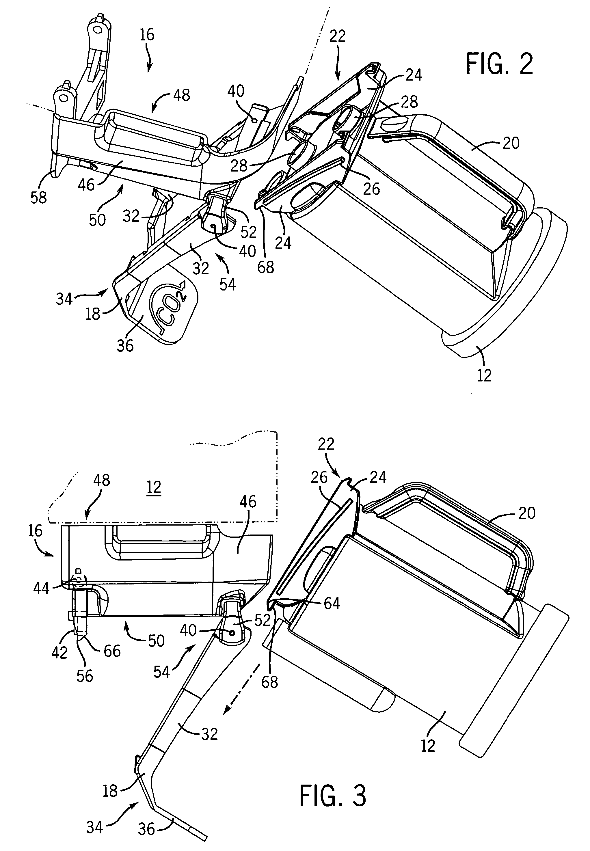
[0022]The present invention pertains to an interface mechanism for removably uniting a carbon dioxide absorption canister with a patient breathing circuit of a ventilator. It should be recognized that the following detailed description and attached figures are an exemplification of the principles of the invention, which is more particularly defined in the appended claims. The invention is not limited to the particular examples shown and described herein.

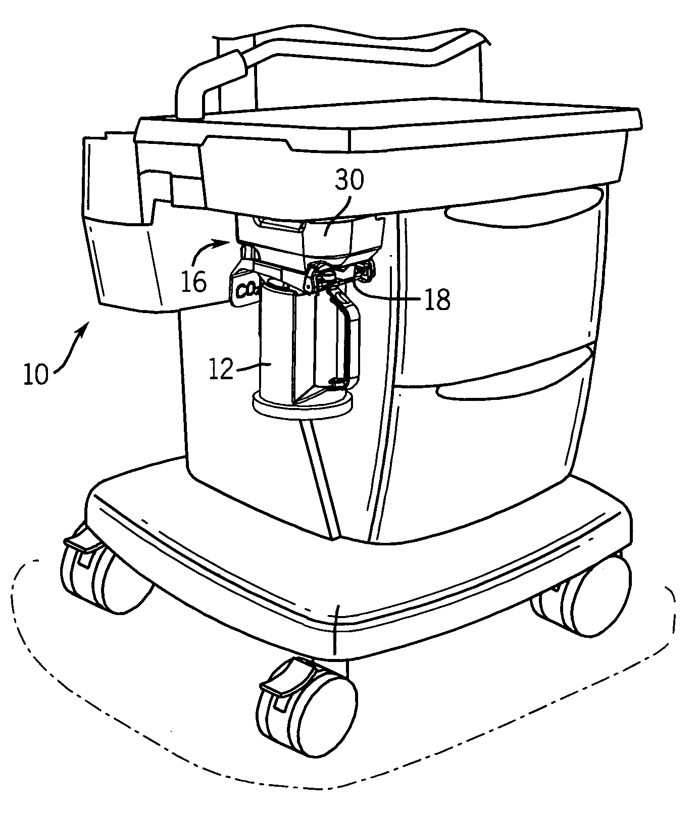
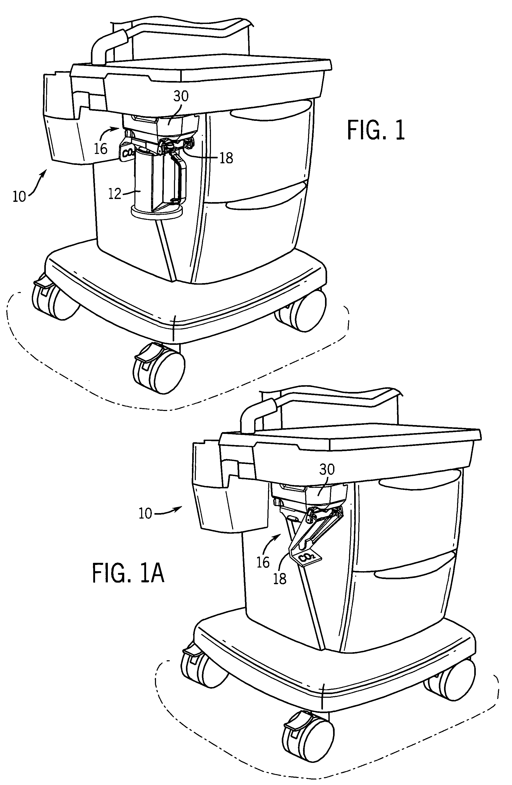
[0023]Referring to FIG. 1, an anesthesia system incorporating a ventilator 10 is shown in perspective view. The overall flow of gases to and from the ventilator 10 is a generally closed circuit, that is, the patient is connected to a substantially closed loop supply of gases and re-breathes certain of those exhaled gases supplemented by fresh gas. The ventilator 10, therefore, provides a quantity of gas containing a predetermined metered quantity of anesthetic agent along with other gases such as N2O and, of course, a life-sustaining...


PUM


Abstract

An interface mechanism is provided that removably unites a carbon dioxide absorption canister with a patient breathing circuit on a ventilator. The interface mechanism includes a cradle that is moveably positioned between a first position and a second position, wherein in the first position, the canister is coupled to the cradle and the cradle is positioned such that the canister is in fluid communication with the breathing circuit. In the second position, the canister is removable from the cradle and the cradle extends at an angle from the patient breathing circuit. The interface mechanism advantageously provides visual indication when the canister is removed and the breathing circuit is operating as a closed loop system, without CO2 filtration. The mechanism also facilitates efficient and accurate fluid connection between the carbon dioxide absorption canister and the breathing circuit.

Description

BACKGROUND OF THE INVENTION[0001]The present invention relates to anesthesia systems used to provide an anesthetic agent to a patient.[0002]In general, anesthesia systems are utilized in medical settings and comprise various equipment to anesthetize the patient and maintain the patient in an anesthetized state until an operation or procedure is completed. Such systems typically comprise various pressure regulators, flow control devices, gas mixing devices and vaporizers to vaporize a volatile liquid anesthetic and to introduce the anesthetic laden gases into the patient. The patient is connected to the system by means of a face mask or other device and which interfaces with the anesthesia system via a patient circuit that may typically have an inspiratory limb through which the gases are introduced into the patient and an expiratory limb that conveys the exhaled gases from the patient. Such limbs may be separate conduits joined by a wye piece at or near the patient or may comprise c...

Claims


Application Information

Patent Timeline
Patent Type & Authority Patents(United States)
IPC IPC(8): A62B7/10A61M16/00A62B9/00A62B23/02A62B7/00A61M15/00
CPCA61M16/186A61M16/22A61M16/01A61M16/208A61M2205/12A61M2205/583Y10T24/266A61M2209/084Y10T24/268Y10T24/264Y10T24/26Y10T24/262A61M2209/082Y10T292/0917Y10T292/0886Y10T292/0871Y10T292/0803Y10T292/0969
Inventor MASHAK, JAMES N.
Owner GENERAL ELECTRIC CO
Learn More