
Civil engineering structure, individual construction element and method for reinforcing such a structure

a technology of civil engineering and construction elements, applied in bulkheads/piles, soil preservation, roads, etc., can solve problems such as landslides, deformation and damage of exposed faces of barricades, and the disadvantage of existing concrete structures cracking or being downright destroyed

Inactive Publication Date: 2008-09-16
FRANCE GABION ZONE IND
View PDF20 Cites 30 Cited by
  • Summary
  • Abstract
  • Description
  • Claims
  • Application Information

AI Technical Summary

Benefits of technology

"The invention is a new type of civil engineering structure that can protect against impacts of moveable masses, such as stones, and is easy to repair. The structure is made up of individual construction elements that can be easily replaced if damaged. These elements are secured to one another and filled with a material that can deform elastoplastically, such as shredded tyres or polystyrene. The structure can be prefabricated outside of hazardous zones and can be reinforced to withstand high impacts. The invention also includes a method for reinforcing existing protective structures. The main technical effects of the invention are improved protection against impacts, easier repair, and better aesthetic and ecological appearance."

Problems solved by technology

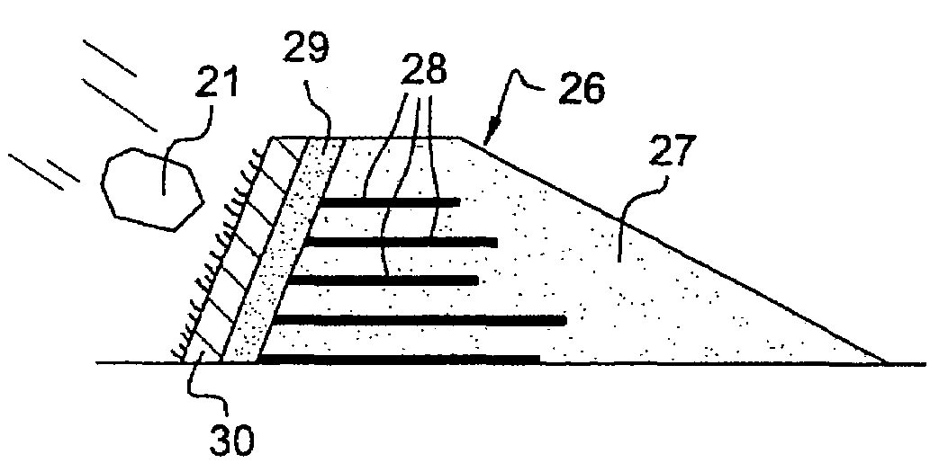
In mountainous regions and in all steep places, the roads, railway lines and residential areas are often threatened with falls of stones, landslides and slumps coming from cliffs or overhanging slopes.
Where high impacts are concerned, the exposed face of the barricades may be deformed and damaged.
The existing concrete structures also have the disadvantage of cracking or of being downright destroyed in the event of impacts by moveable masses having high kinetic energy.
Moreover, these infrastructures have much larger dimensions in relation to the actual protection requirements.
To be precise, it is extremely difficult to conduct a diagnosis on a damaged barricade.
This renovation is a cumbersome operation which also has to be carried out in especially hazardous locations subject to stone falls.
Furthermore, the addition of elements which seem like refuse gives the structures an aesthetic appearance which is not necessarily acceptable.
A second problem is to design a structure having mechanical properties such that it doesn't require overdimensioning in order to ensure its protective functions.
A third problem is to improve the aesthetic and ecological appearance of the structures, whilst at the same time preserving their functional appearance.
A fourth problem is to develop an individual construction element capable of limiting the damage undergone by the entire civil engineering structure with which it is associated.
A fifth problem is to produce an element which can be prefabricated outside the hazardous zones, that is to say those subject to stone falls.
A sixth problem is to implement a method making it possible to reinforce a pre-existing protective structure.

Method used


Image

  • Civil engineering structure, individual construction element and method for reinforcing such a structure
  • Civil engineering structure, individual construction element and method for reinforcing such a structure
  • Civil engineering structure, individual construction element and method for reinforcing such a structure

Examples


first embodiment

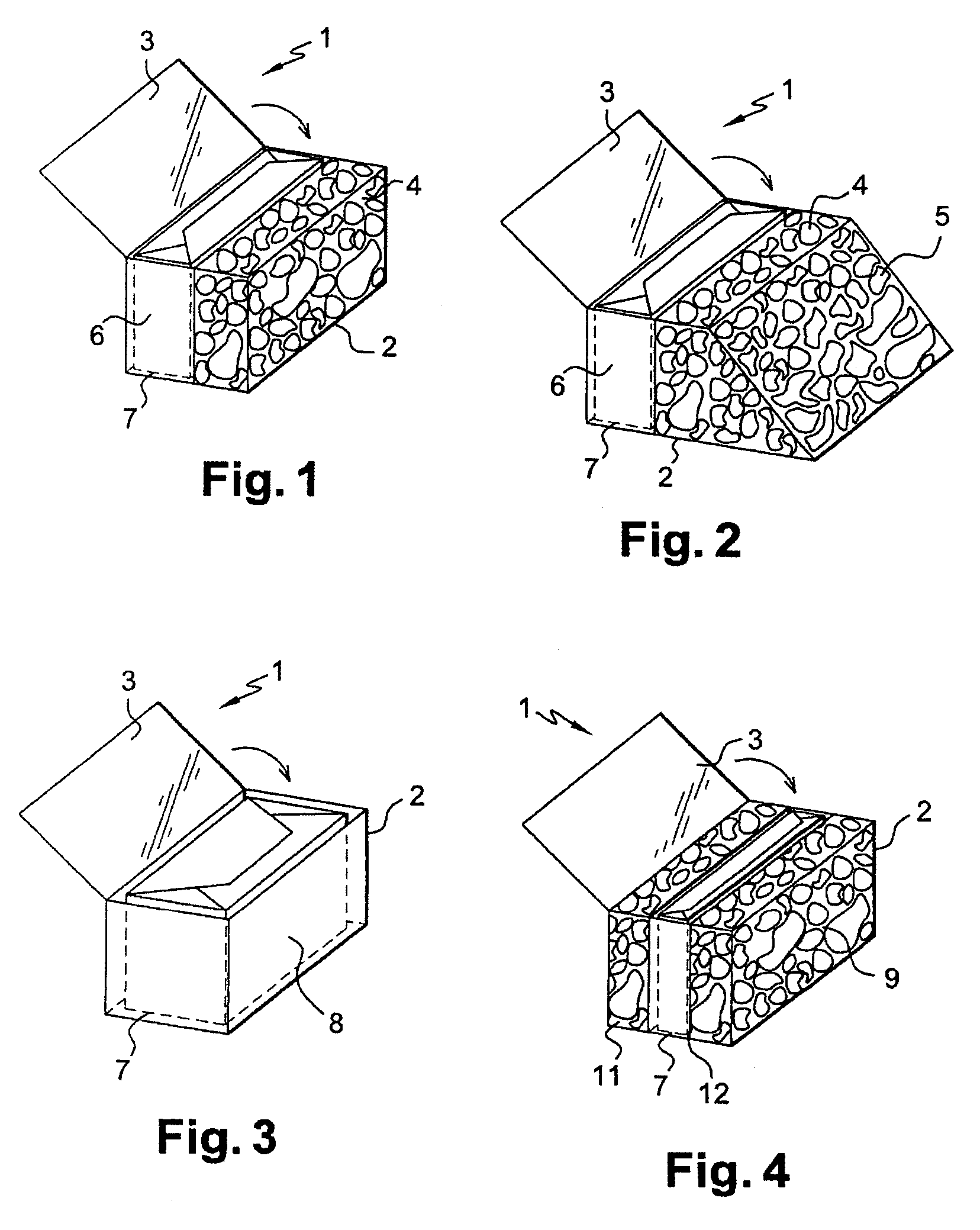
[0035]It will be noted that, depending on the desired function, the arrangement of the two volumes (4 and 6) may be reversed, as compared with FIG. 1. The first volume containing loose materials (4) may be arranged at the rear and the second volume containing materials having elastoplastic properties (6) may be arranged at the front on the same side as that face of the protective structure which is exposed to impacts.

[0036]In a second embodiment (see FIG. 2), the cage (2) likewise has the same two distinct volumes (4 and 6). However, the front face (5) exposed to impacts has an inclination, for example substantially equal to 45° with respect to the horizontal. Such an inclined front face (5) will allow a much easier establishment of plants, thus giving the cage (2) and the entire structure obtained by means of this type of cage (2) a much more attractive aesthetic and ecological appearance.

[0037]In a third embodiment (see FIG. 3), the cage (2) has a single volume (8). This single vo...

second embodiment

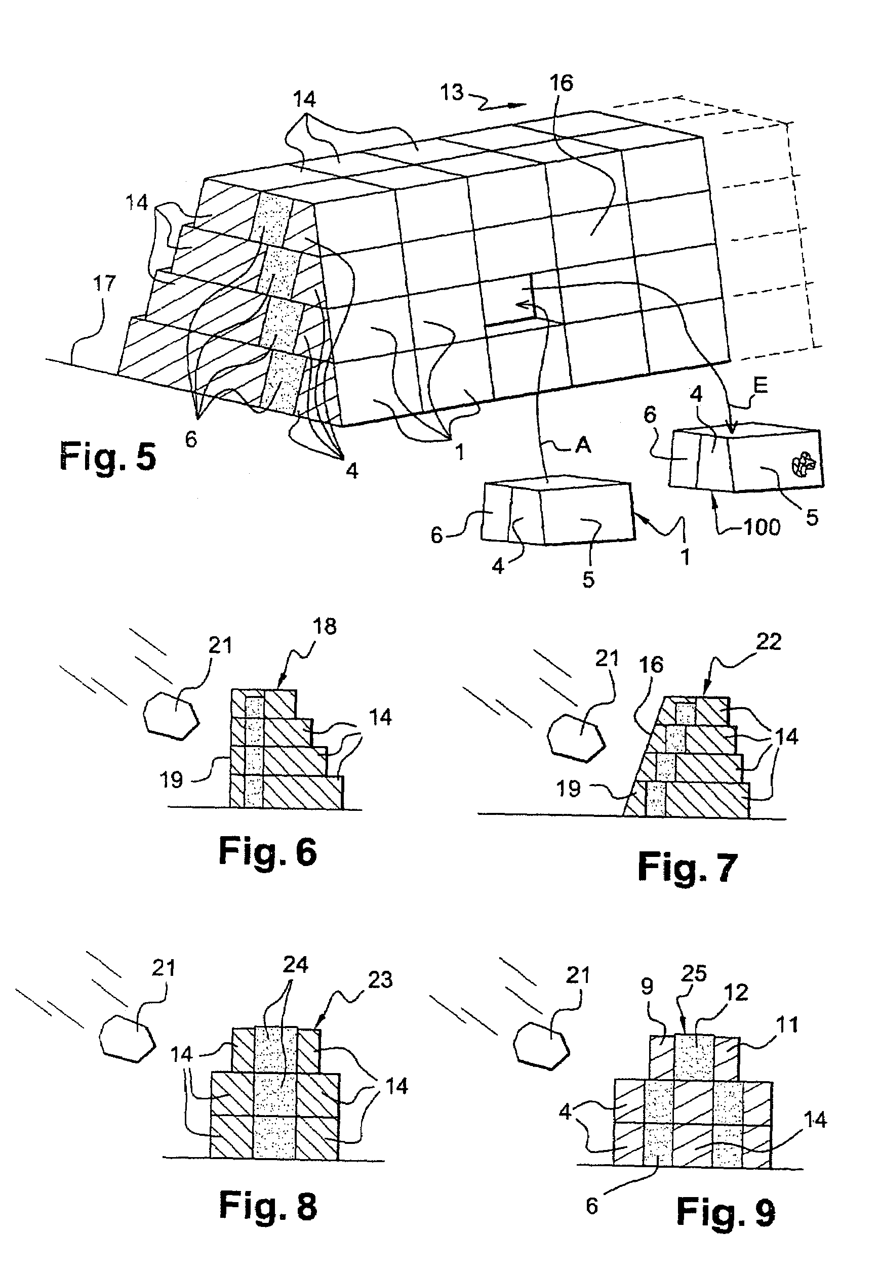
[0040]According to one aspect of the invention, the structure (13) comprises a facing (16) produced from removeable characteristic individual construction elements. In this example, sleet-pile cells having an inclined front face (1) and conforming to FIG. 2 are used. These sheet-pile cells (1) are arranged with respect to one another and with respect to the conventional sheet-pile cells of the stack (14), in such a way as to have their first volume with loose material (4) on the exposed front face and to have their second volume with elastoplastic material (6) at the rear and against the sheet-pile cells of the stack (14).

[0041]According to another aspect of the invention, the sheet-pile cells of the facing (1) are easily removable and can be replaced if they are damaged. Thus, the method for repairing a civil engineering structure (13) may comprise the steps involving:[0042]determining the individual construction element or individual construction elements, filled with a material h...


PUM

PropertyMeasurementUnit
interior volumesaaaaaaaaaa
interior volumeaaaaaaaaaa
volumeaaaaaaaaaa

Abstract

A civil engineering structure, intended for ensuring protection against impacts of moveable masses, has a face exposed to the impacts of moveable masses. The structure includes, in the region of the face exposed to the impacts of moveable masses, a set of individual construction elements secured to one another and filled completely or partially with at least one material having a capacity for being deformed elastoplastically, the individual construction elements liable to be damaged by impacts of moveable masses being capable of being replaced individually by similar individual construction elements.

Description

[0001]This application claims the benefit of French Application 03.50644, filed Oct. 3, 2003, the entirety of which is incorporated herein by reference.[0002]The present invention relates to a civil engineering structure ensuring protection against impacts of moveable masses and of projectiles, more particularly of stones. It also relates to an individual construction element intended for the production of protective structures in the field of civil engineering and public works. Another aspect of the invention is concerned with a method for reinforcing a structure ensuring protection against impacts.PRIOR ART[0003]In mountainous regions and in all steep places, the roads, railway lines and residential areas are often threatened with falls of stones, landslides and slumps coming from cliffs or overhanging slopes. Thus, in spite of regular drainages of cliffs, infrastructures are additionally provided, which are interposed between the zone to be protected and the sources of projectile...

Claims


Application Information

Patent Timeline
Patent Type & Authority Patents(United States)
IPC IPC(8): E02D29/02E01F7/04
CPCE01F7/045E02D29/0208E02D2300/0062E02D2300/0003
Inventor DERACHE, FRANCIS
Owner FRANCE GABION ZONE IND
Learn More