Agitator loading system

a technology of agitator and loading bay, which is applied in the direction of liquid bottling, packaging goods type, special packaging, etc., can solve the problems of noise emission, slow batching time, traffic management and agitator maneuverability, etc., and achieve the effect of minimizing dust dispersion

Active Publication Date: 2008-09-23
INTRAY CONSOL
View PDF15 Cites 10 Cited by
  • Summary
  • Abstract
  • Description
  • Claims
  • Application Information

AI Technical Summary

Benefits of technology

[0006]The present invention provides an agitator loading, including a loading bay, a delivery chute for delivering mixture ingredients from a storage area, and a dust containment apparatus for minimizing dust dispersion during agitator loading.
[0007]Preferably, the delivery chute is movable between a retracted position and at least one extended position. The delivery chute may extend between the storage area and an inlet on the agitator, when in the extended position. The delivery chute can have two extended positions, or more than two, which positions the delivery chute at variable heights below the storage area. This variable height delivery chute allows agitators of different heights to all use the one agitator loading system.
[0009]Advantageously, the dust containment apparatus includes a door for closing one end of the loading bay. Alternatively, two doors may be included for closing both ends of the loading bay. The dust containment apparatus may also include a dust hood. The dust hood is preferably moveable between a retracted position and a lowered position for minimizing dust dispersion during agitator loading. Advantageously, the dust hood extends below the agitator inlet when in the lowered position. The dust containment apparatus may also include an extractor. The inlets of the extractor are preferably located within the dust hood when the dust hood is lowered.

Problems solved by technology

The agitator loading system in current concrete batching plants is slow, resulting in slow batching times as well as traffic management and agitator maneuverability concerns.
Dust emission out of the open end of the loading bay is a problem, as is noise emission.
There is a large amount of spillage and waste of the ingredients and water, thus the loading bay needs to be constantly cleaned.

Method used


Image

  • Agitator loading system
  • Agitator loading system
  • Agitator loading system

Examples


Embodiment Construction

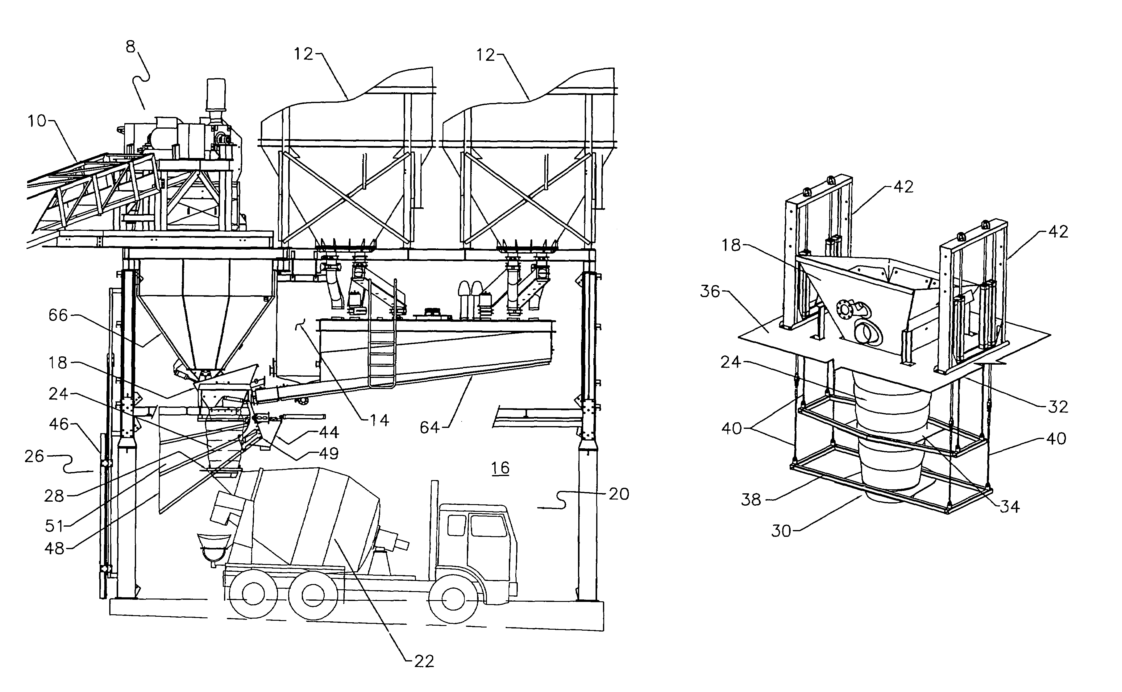
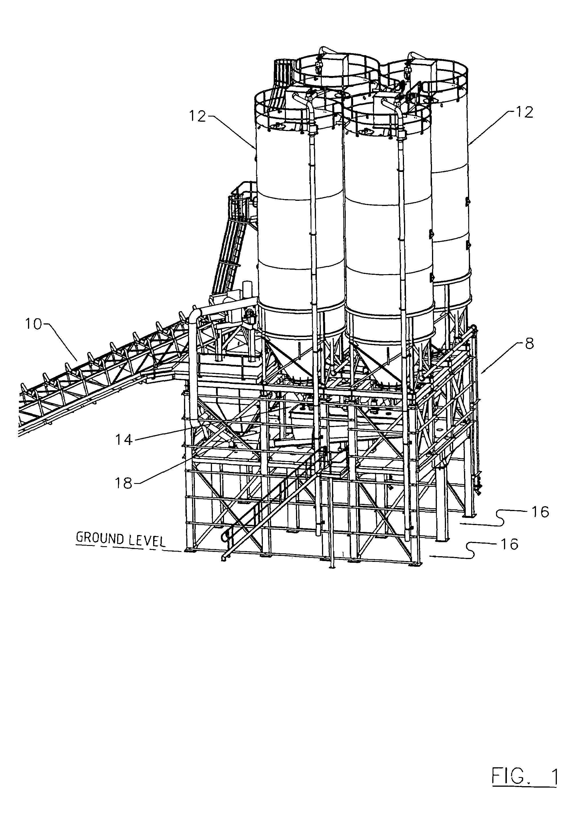
[0027]FIG. 1 shows a perspective view of part of a concrete batching plant. Aggregate is delivered to a storage area 8 via a conveyor 10. Cement is stored in silos 12 and water is stored in water tank 14. Aggregate, cement and water are mixture ingredients that are delivered to a gob hopper 18 within the storage area 8. Beneath silos 12 are two loading bays 16, although any number of loading bays 16 could be incorporated in other embodiments of the invention.

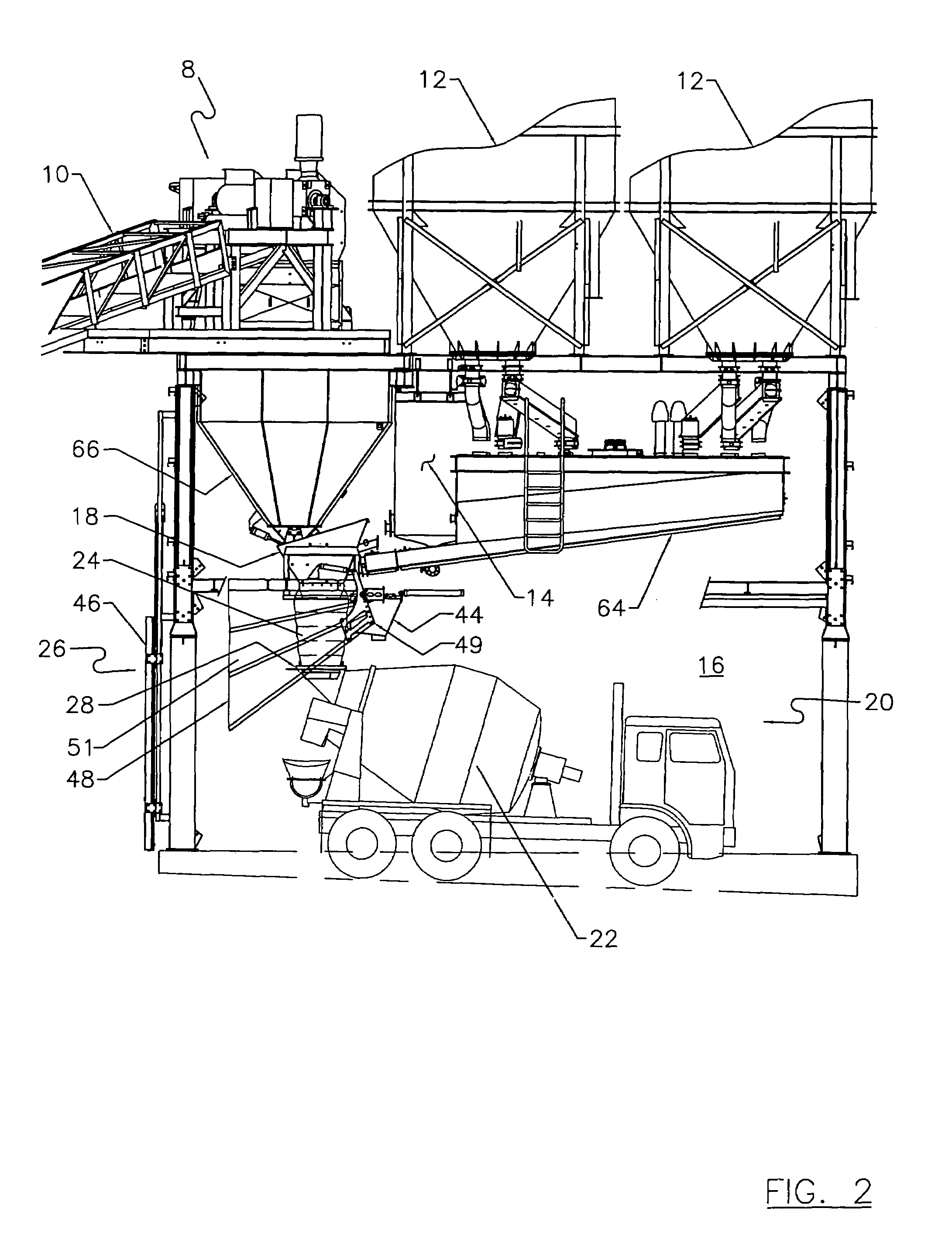
[0028]An agitator loading system 20 is shown in FIG. 2. The agitator loading system 20 is used for loading mixture ingredients into an agitator 22. The system 20 includes a loading bay 16, a delivery chute 24 and a dust containment apparatus 26. Loading bay 16 includes two side walls, with open ends that allow an agitator to drive through the loading bay 16, improving traffic flow over known systems. The delivery chute 24 delivers mixture ingredients from the gob hopper 18 to an inlet 28 on the agitator 22. The dust containment ...


PUM

PropertyMeasurementUnit
transparentaaaaaaaaaa
dust dispersionaaaaaaaaaa
heightsaaaaaaaaaa

Abstract

An agitator loading system for loading mixture ingredients, the system includes a loading bay, a delivery chute for delivering mixture ingredients from a storage area, and a dust containment apparatus for minimizing the dust dispersion during agitator loading. A method for loading an agitator from an agitator loading system is also described.

Description

FIELD OF THE INVENTION[0001]The present invention relates to an agitator loading system. Particularly, the present invention relates to the loading of mixture ingredients into an agitator at a concrete batching plant.BACKGROUND OF THE INVENTION[0002]Concrete batching plants must adhere to strict statutory requirements regarding the control of environmental conditions. One area that requires particular attention is the loading of mixture ingredients, for use in making concrete, into an agitator.[0003]The mixture ingredients of concrete typically include aggregate, such as sand and gravel, cement and water. Each ingredient is separately stored and delivered to a gob hopper, which feeds the mixture into the loading inlet of an agitator. The loading of the agitator occurs in a loading bay, which is enclosed on three sides, such that the agitator is reversed into the bay. The enclosed loading bay is designed to reduce the amount of dust emission into the surrounding environment. When loa...

Claims


Application Information

Patent Timeline
Patent Type & Authority Patents(United States)
IPC IPC(8): B65G65/30B65B1/28B65G69/18
CPCB28C7/0481
Inventor GALIJAN, MICHAEL N.
Owner INTRAY CONSOL
Why Eureka
Try Eureka