Continuously variable transmission

a transmission and continuously variable technology, applied in the direction of gearing, gearing details, hoisting equipment, etc., can solve the problems of unnecessarily difficulty in increasing the length of each fan blade, and reducing the service life of the fan blade, so as to reduce the amount of jumbo-sized continuously variable transmission, enhance the durability of the drive belt, and suppress the back pressure disturbing the flow of discharged cooling air.

Inactive Publication Date: 2008-09-23
SUBARU CORP
View PDF8 Cites 69 Cited by
  • Summary
  • Abstract
  • Description
  • Claims
  • Application Information

AI Technical Summary

Benefits of technology

[0008]An object of the present invention is to improve the durability of a continuously variable transmission by sufficiently cooling the interior of the case of the continuously variable transmission.
[0012]According to the present invention, the scroll surface is formed from the cooling-air intake region to the cooling-air discharge region so as to be gradually away from the top faces of the fan blades. Consequently, back pressure disturbing the flow of the discharged cooling air can be suppressed, whereby the blowing efficiency of the cooling air can be enhanced.
[0013]Therefore, since the interior of the case can be sufficiently cooled, the durability of the drive belt can be enhanced and the durability of continuously variable transmission can be also enhanced.

Problems solved by technology

However, the diameter sizes of the primary pulley and secondary pulley on which the fan blades are formed are limited, and the length of each fan blade has been difficult to increase.
Particularly, to increase the length of each fan blade beyond the diameter size of each pulley and / or to increase the width size of each fan blade lead to the unnecessarily jumbo-sized continuously variable transmission.
Since the jumbo-sizing of the fan blades to be formed on the pulleys is thus restricted, it is difficult to increase a flow rate of the cooling air for cooling a interior of the case.
Therefore, the drive belt cannot be sufficiently cooled, whereby there is the problem that the durability of the drive belt is degraded.

Method used


Image

  • Continuously variable transmission
  • Continuously variable transmission
  • Continuously variable transmission

Examples


Embodiment Construction

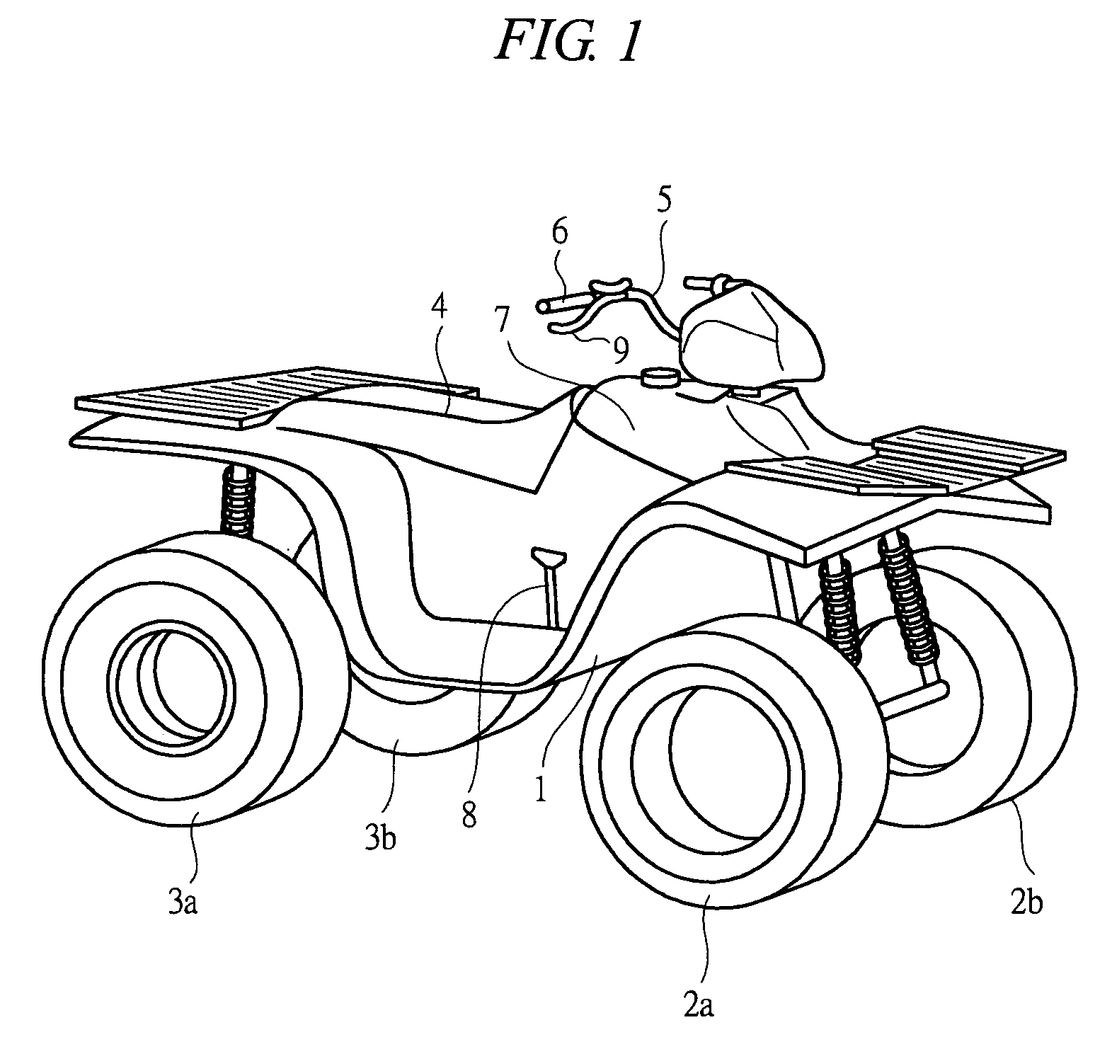
[0019]Hereinafter, an embodiment of the present invention will be detailed with reference to the drawings. FIG. 1 is a perspective view showing a vehicle, and this vehicle is an ATV generally called a “buggy”, namely, an unleveled-ground traveling vehicle. As shown in FIG. 1, a vehicle body 1 is provided with front wheels 2a and 2b and rear wheels 3a and 3b, and a saddle-type seat 4 is provided in a central portion of the vehicle body 1. A rider rides on the vehicle by straddling the seat 4 and operates a steering handle 5 to make the vehicle run.

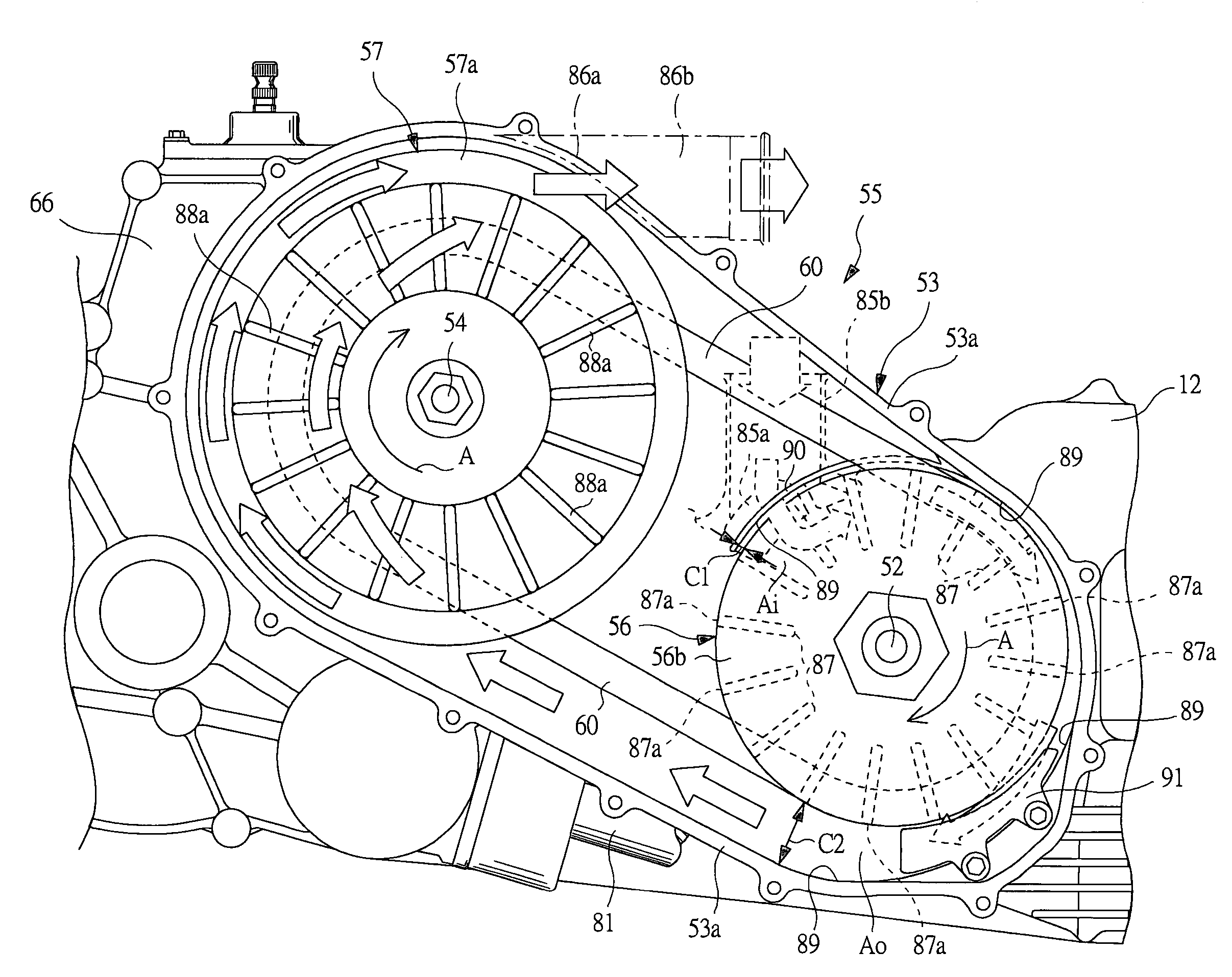
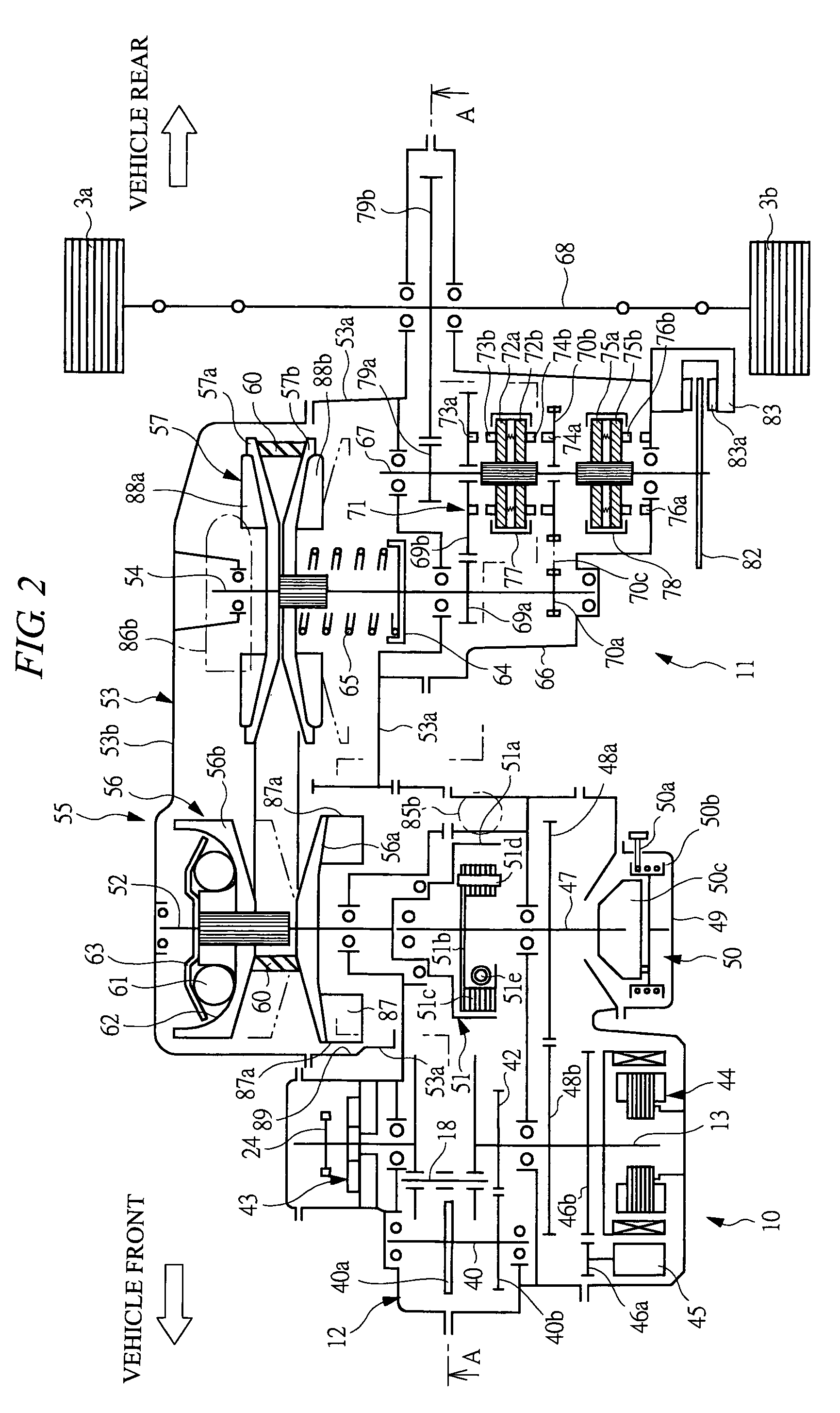
[0020]FIG. 2 is a schematic view showing an engine unit 10 and a drive unit 11 that are mounted in the vehicle in FIG. 1. FIG. 3 is a cross-sectional view taken along line A-A of FIG. 2. As shown in FIGS. 2 and 3, the engine unit 10 for outputting an engine power is provided on a vehicle-front side. On a vehicle-rear side, there is provided the drive unit 11 transmitting the engine power to drive wheels via a continuously variable transmiss...


PUM


Abstract

Cooling efficiency of cooling air is enhanced and durability of a continuously variable transmission is improved. The continuously variable transmission to be mounted on a vehicle has a transmission case. A primary pulley driven by an engine and a primary pulley linked to drive wheels are rotatably accommodated in the transmission case. A V-belt is provided to extend for winging between the primary pulley and the secondary pulley, and the rotation of the primary pulley is continuously changed and transmitted to the secondary pulley. Fan blades are formed in the primary pulley, and a scroll surface is formed in transmission case from an intake region of the cooling air toward a discharge region thereof so as to gradually away from top faces of the fan blades in a radial-outer direction. Thereby, blowing efficiency of the cooling air can be enhanced and an interior of the transmission case can be sufficiently cooled, whereby the durability of the V-belt can be enhanced.

Description

BACKGROUND OF THE INVENTION[0001]The present invention relates to a continuously variable transmission to be mounted on a vehicle and, specifically, to a technique effectively applied to a continuously variable transmission having a rubber drive belt.[0002]A belt-driven continuously variable transmission (CVT) applied to a power transmission system of the vehicle has a primary pulley provided on an input shaft and a secondary pulley provided on an output shaft, wherein the drive belt is provided to extend for winding between the two pulleys. By changing the contact diameter of the drive belt, a rotation speed transmitted from the input shaft to the output shaft is changed continuously.[0003]In such a continuously variable transmission, the contact diameter of the drive belt is changed. Therefore, there are a hydraulic type one in which a groove width of the primary pulley is variably controlled by hydraulic pressure in accordance with a run condition, and a weight type one in which ...

Claims


Application Information

Patent Timeline
Patent Type & Authority Patents(United States)
IPC IPC(8): F16H57/04F16H55/56F16H9/12F16H57/027F16H57/035F16H57/05
CPCF16H57/05F16H57/0489F16H57/0415B60Y2200/124
Inventor CHONAN, MITSUGI
Owner SUBARU CORP
Why Eureka
Try Eureka